Schematic Diagram
INTRODUCTION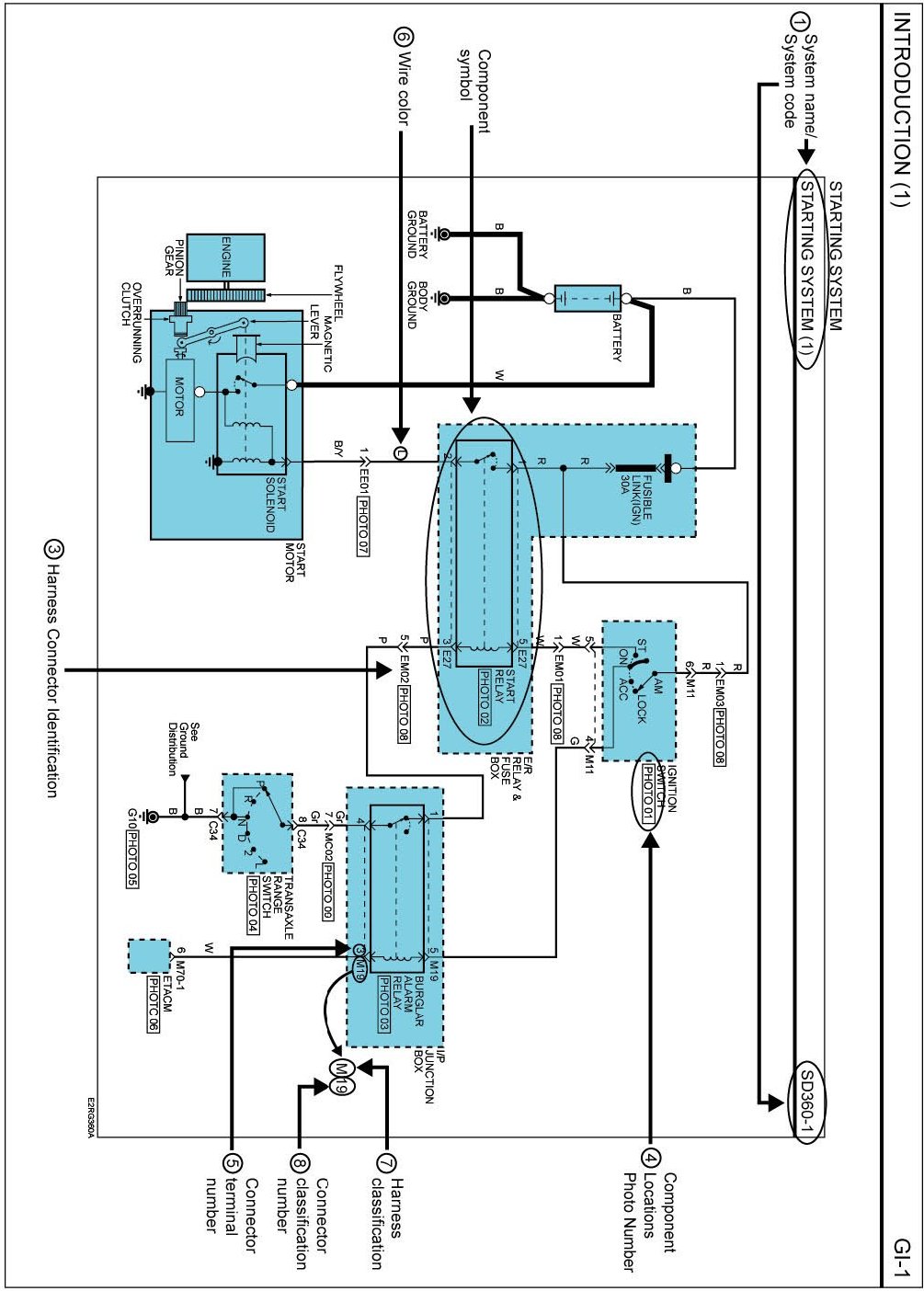
1. Pages by system/Name of schematic diagram
- Each schematic diagram provides data related to current flow, switch functionality (where applicable), and related circuit information.
- Understanding circuit operation is a critical component of effective diagnosis.
- The schematic diagram index provides a guide to locating the correct circuit.
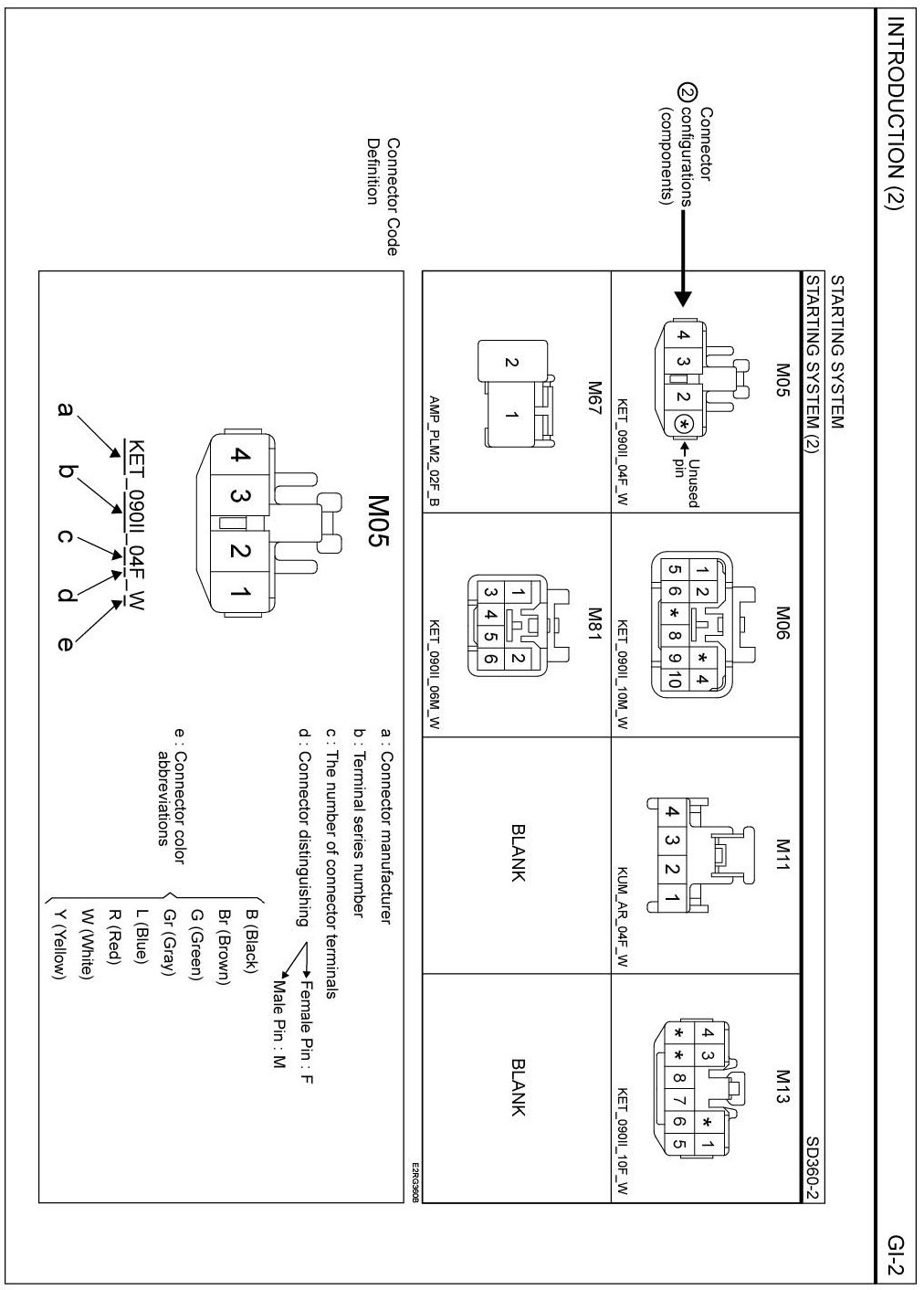
2. Connector configuration (components)
- The pages following the schematic diagrams contain data related to component connector configuration. Each page shows a terminal side view of the connector. Refer to the "Connector View and Numbering Order" section in this document for information related to terminal numbering.
NOTE: a "*" symbol in place of terminal number indicates an unused terminal (connector cavity will be empty).
3. Connector configurations (connection between harnesses)
- The "connector Configurations" section identifies connectors that are used to join harness together, junction connectors for common power and ground wires are also identified in this section. Male and female connector view are shown applicable.
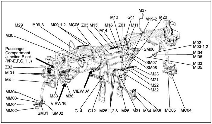
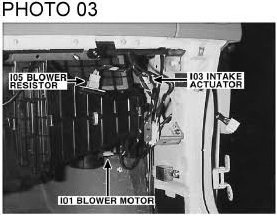
4. Component locations
- Schematic diagrams include references to images found in the "Component Locations" section of this document. These images show components and connector's in their installed location on the vehicle.
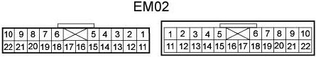
5. CONNECTOR VIEW AND NUMBERING ORDER
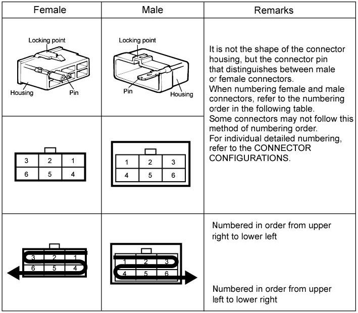
NOTE: UNLESS OTHERWISE STATED, ALL CONNECTOR VIEWS ARE FROM THE TERMINAL SIDE OF THE CONNECTOR
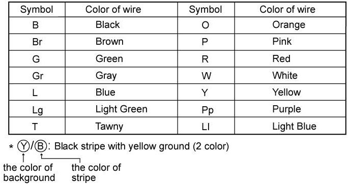
6. WIRE COLOR ABBREVIATIONS
The following abbreviations are used to identify wire colors in the circuit schematics.
7. HARNESS CLASSIFICATIONS
Electrical wiring connectors are classified according to the wiring data in the Harness Layouts.
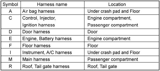
*It depends on vehicles, it is necessary too check the harness name information on the harness layouts for detailed information.
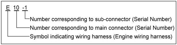
8. CONNECTOR IDENTIFICATION
A connector identification symbol consists of a wiring harness location classification symbol corresponding to a wiring harness location and number corresponding to the connector.
These connector location can be found in the HARNESS LAYOUTS.
For example:
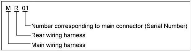
NOTE: Connectors which connect each wiring harness are represented by the following symbols.
For example:
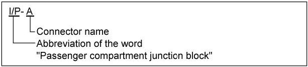
JUNCTION BLOCK IDENTIFICATION
A Junction block identification symbol consists of a wiring harness location classification symbol corresponding to a wiring harness location and number corresponding to the connector in the junction block.
For example:
HARNESS LAYOUTS
Harness layouts show the routing of the major wiring harness, the in-line connectors and the splices between the major harness. These layouts will make electrical troubleshooting easier.