Understanding the Circuit Diagrams
Understanding The Circuit Diagrams
Components

After each component description, a translation code is displayed in brackets, for example: Starter relay (R102), Engine Control module (ECM)(D131). The codes can be ignored.
Note:A dotted outline indicates that the component identified is not shown in its entirety.
Connectors
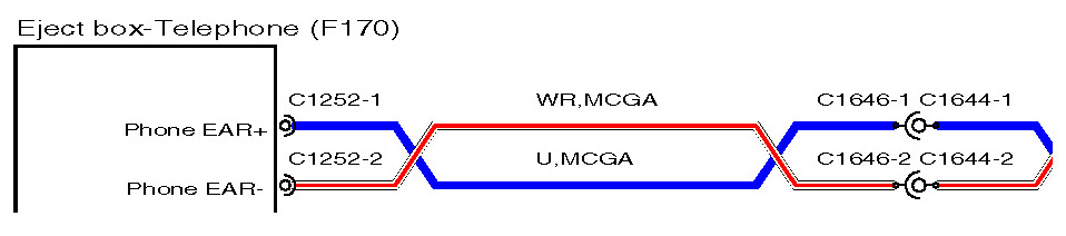
Connectors and header joints are identified by their corresponding connector number with a numbered suffix to indicate the pinout detail of the wire, i.e. C0292-1 identifies connector 292, pin number 1. Wire insulation colours are listed in a table at the end of this section. Where wires have a predominant colour with a secondary colour tracer, the main colour is identified first, i.e. WH-BK
- white with a black tracer.
Line Types
Crossed wires as illustrated above show an example of how a twisted pair of wires may be represented on the circuits.
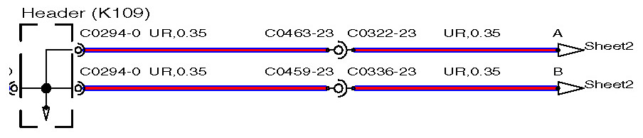
The arrows illustrated above show an example of the page break symbols, identifying that the circuit continues at the corresponding letter on the sheet number indicated.
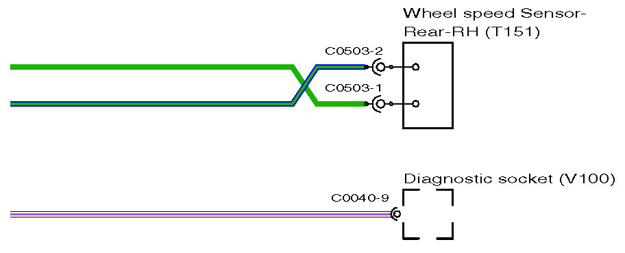
The cup and ball symbol represents the male and female halves of connector. Most connectors plug directly into a component but some are wired directly to the component using a "flylead" as with C503 above.
Colour Codes
