Inspection
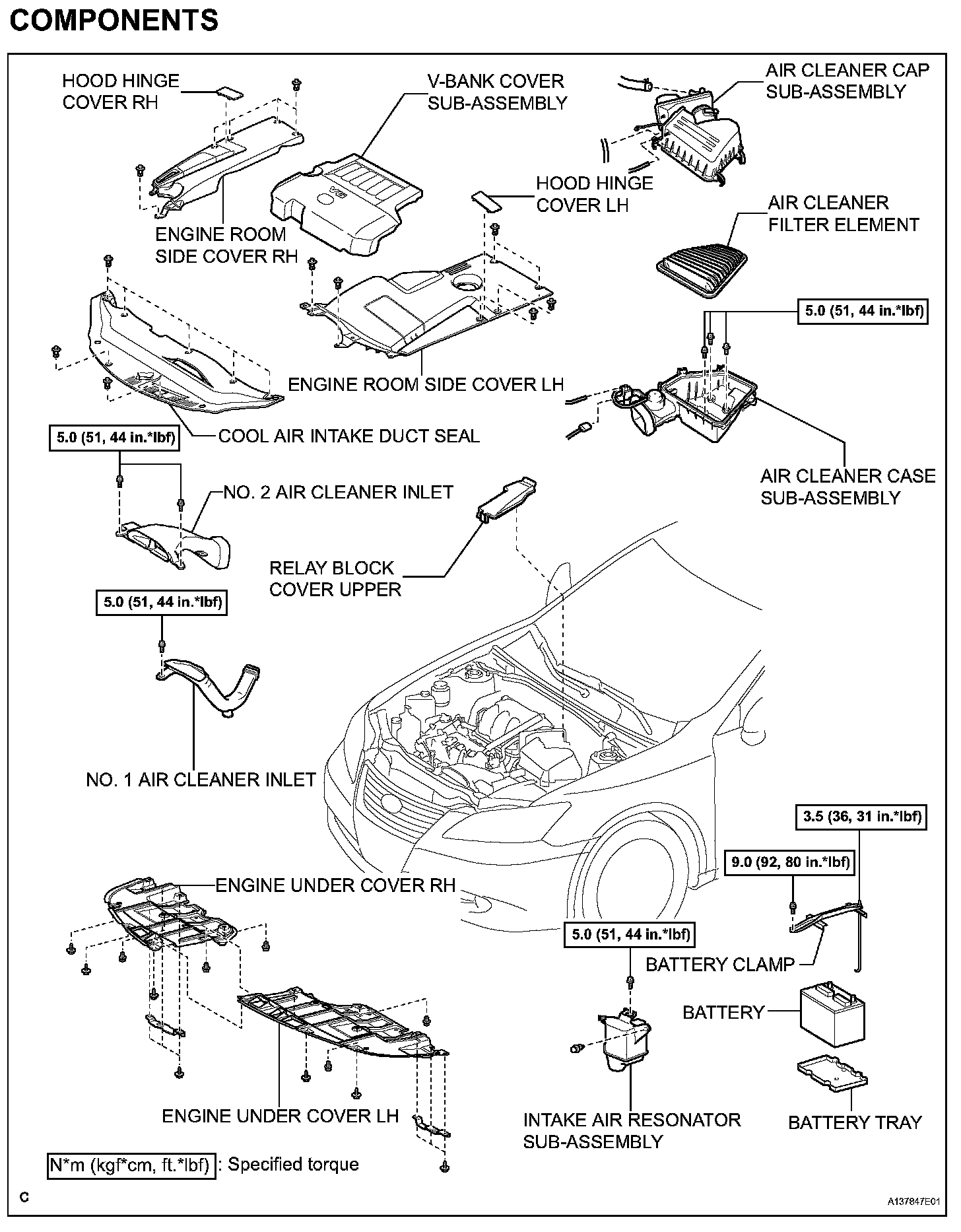
ENGINE ASSEMBLYCOMPONENTS (Part 1):
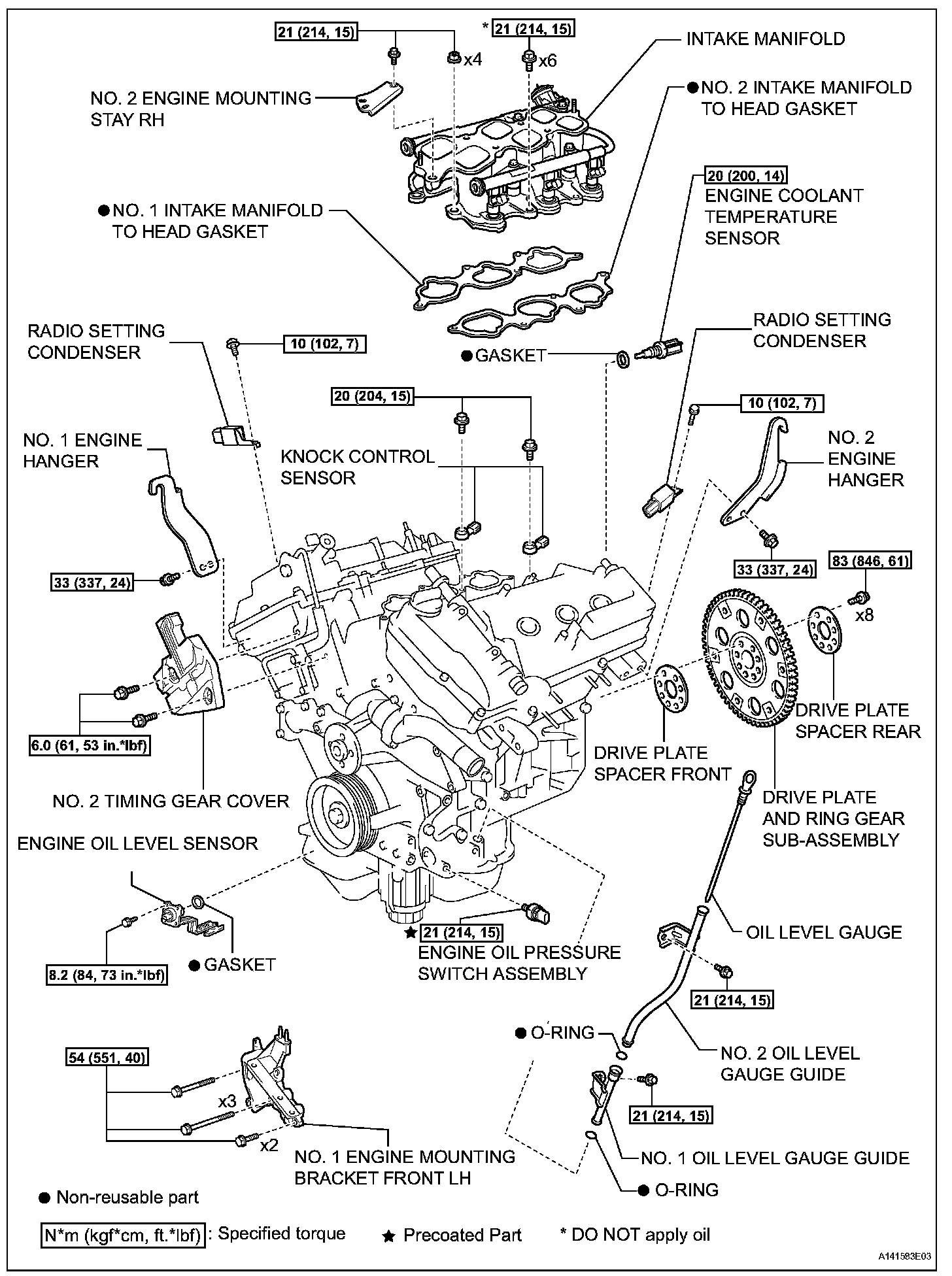
COMPONENTS (Part 2):

COMPONENTS (Part 3):

COMPONENTS (Part 4):

COMPONENTS (Part 5):

COMPONENTS (Part 6):

COMPONENTS (Part 7):

COMPONENTS (Part 8):
INSPECTION

1. INSPECT EXHAUST MANIFOLD SUB-ASSEMBLY LH
(a) Using a precision straightedge and feeler gauge, measure the warpage on the contact surface of the cylinder head.
Maximum warpage: 0.7 mm (0.028 in.)
HINT: The maximum allowable warpage of each installation surface is 0.3 mm (0.012 in.).
If the warpage is greater than the maximum, replace the manifold.

2. INSPECT EXHAUST MANIFOLD SUB-ASSEMBLY RH
(a) Using a precision straightedge and feeler gauge, measure the warpage on the contact surface of the cylinder head.
Maximum warpage: 0.7 mm (0.028 in.)
HINT: The maximum allowable warpage of each installation surface is 0.3 mm (0.012 in.).
If the warpage is greater than the maximum, replace the manifold.

3. INSPECT INTAKE AIR SURGE TANK ASSEMBLY
(a) Using a precision straightedge and feeler gauge, measure the warpage on the contact surface of the intake manifold.
Maximum warpage: 2.5 mm (0.098 in.)
If the warpage is greater than the maximum, replace the surge tank.

4. INSPECT INTAKE MANIFOLD
(a) Cylinder head side:
(1) Using a precision straightedge and feeler gauge, measure the surface contacting the cylinder head for warpage.
Maximum warpage: 0.1 mm (0.003 in.)
If the warpage is greater than the maximum, replace the intake manifold.
(b) Surge tank side:
(1) Using a precision straightedge and feeler gauge, measure the surface contacting the surge tank for warpage.
Maximum warpage: 0.1 mm (0.003 in.)
If the warpage is greater than the maximum, replace the intake manifold.