Rear
REAR BRAKECOMPONENTS:
COMPONENTS:
REMOVAL
HINT:
^ Use the same procedures for the LH side and RH side.
^ The procedures listed are for the LH side.
1. REMOVE REAR WHEEL
2. DRAIN BRAKE FLUID
NOTICE: Wash off brake fluid immediately if it comes in contact with any painted surface.
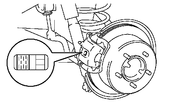
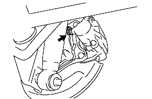
3. CHECK BRAKE PAD LINING THICKNESS
a. Check the pads' lining thickness through the cylinder inspection hole.
Minimum thickness: 1.0 mm (0.039 inch)
If the pads' lining thickness is equal to or less than the minimum, replace the pads.
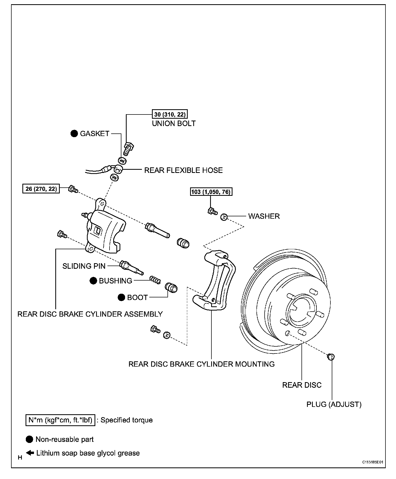
4. DISCONNECT REAR FLEXIBLE HOSE
a. Remove the union bolt and 2 gaskets.
b. Disconnect the flexible hose from the brake cylinder.
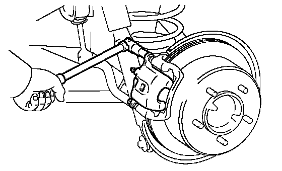
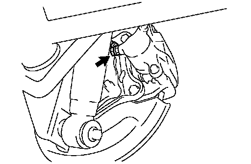
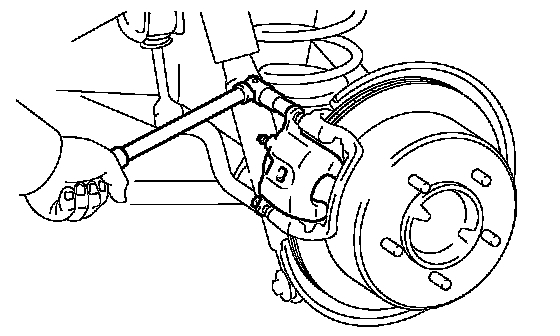
5. REMOVE REAR BRAKE CYLINDER ASSEMBLY
a. Hold the sliding pin and loosen the 2 installation bolts.
b. Remove the 2 installation bolts.
c. Remove the cylinder from the cylinder mounting.
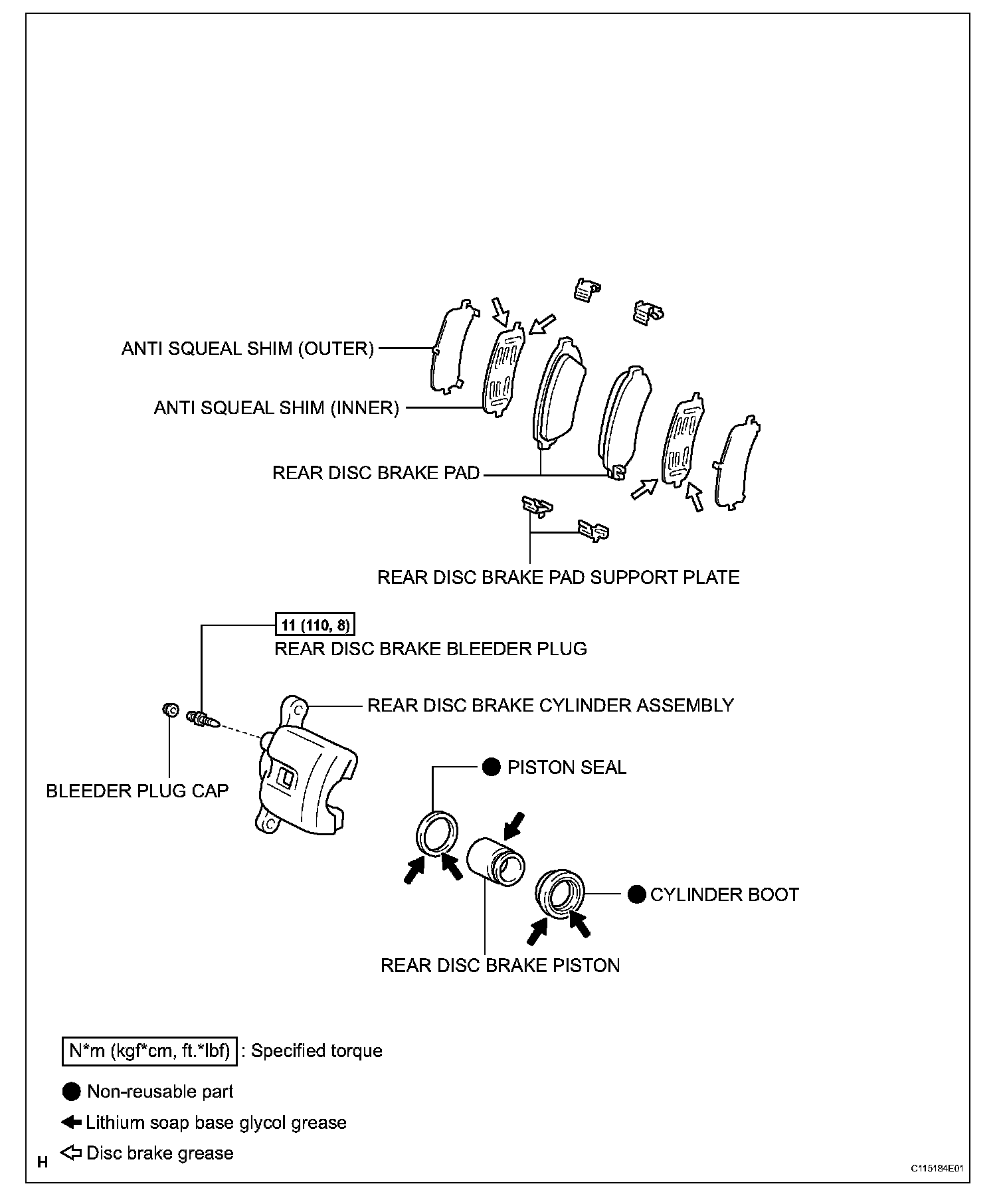
6. REMOVE REAR DISC BRAKE PAD
a. Remove the 2 disc brake pads with anti squeal shims.
7. REMOVE ANTI SQUEAL SHIM
a. Remove the inner and outer anti squeal shims from each pad.
8. REMOVE REAR DISC BRAKE PAD SUPPORT PLATE
a. Remove the 4 plates from the cylinder mounting.
9. REMOVE REAR DISC BRAKE CYLINDER MOUNTING
a. Remove the 2 bolts, washer and cylinder mounting.
DISASSEMBLY
HINT:
^ Use the same procedures for the LH side and RH side.
^ The procedures listed are for the LH side.
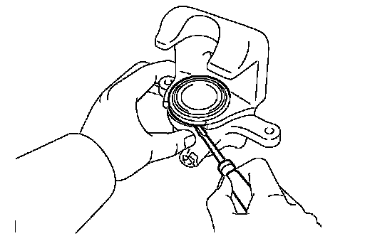
1. REMOVE CYLINDER BOOT
a. Using a screwdriver, remove the cylinder boot from the cylinder.
NOTICE: Be careful not to damage the brake piston and cylinder.
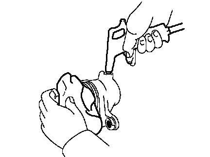
2. REMOVE REAR DISC BRAKE PISTON
a. Place a piece of cloth or similar object between the piston and cylinder.
b. Use compressed air to remove the piston from the cylinder.
CAUTION: Do not place your finger in front of the piston when using compressed air.
NOTICE: Be careful not to spatter the brake fluid.
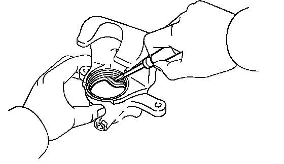
3. REMOVE PISTON SEAL
a. Using a screwdriver, remove the seal from the cylinder.
NOTICE: Be careful not to damage the inner cylinder and cylinder groove.
4. REMOVE SLIDING PIN, BOOT AND SLIDING BUSHING
a. Using a screwdriver and hammer, tap out the pin, boot and bushing.
5. REMOVE REAR DISC BRAKE BLEEDER PLUG
a. Remove the bleeder plug cap and bleeder plug from the cylinder.
6. REMOVE REAR DISC
a. Put matchmarks on the disc and axle hub.
b. Remove the disc.
INSPECTION
1. CHECK BRAKE CYLINDER AND PISTON
a. Check the cylinder bore and piston for rust or scoring.
If necessary, replace the cylinder and piston.
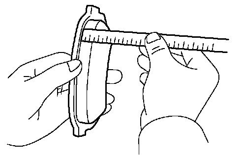
2. CHECK PAD LINING THICKNESS
a. Using a ruler, measure the pad lining thickness.
Standard thickness: 12.0 mm (0.472 inch)
Minimum thickness: 1.0 mm (0.039 inch)
If the pad lining thickness is equal to or less than the minimum, replace the pad.
3. CHECK REAR DISC BRAKE PAD SUPPORT PLATE
a. Check the 4 plates.
HINT: Make sure that the plates have sufficient rebound and are free from deformation, cracks wear, rust and dirt. If necessary, replace the plates.
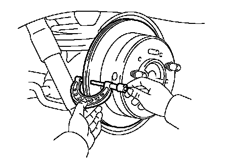
4. CHECK DISC THICKNESS
a. Using a micrometer, measure the disc thickness.
Standard thickness: 18.0 mm (0.709 inch)
Minimum thickness: 16.0 mm (0.611 inch)
If the disc thickness is less than the minimum, replace the disc.
REASSEMBLY
HINT:
^ Use the same procedures for the LH side and RH side.
^ The procedures listed are for the LH side.
1. INSTALL REAR DISC
a. Align the matchmarks and install the disc.
HINT: When replacing the disc with a new one, select the installation position where the disc has a minimum runout.
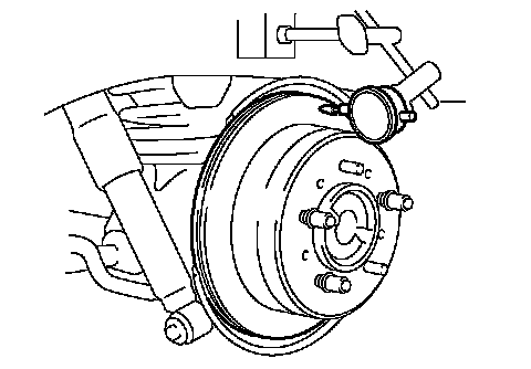
2. CHECK DISC RUNOUT
a. Check the bearing play in the axial direction and check the axle shaft deviation.
b. Temporarily install the disc to the hub with the hub nuts.
c. Using a dial indicator, measure the disc runout 10.0 mm (0.39 inch) away from the outer edge of the disc.
Maximum disc runout: 0.1 mm (0.0040 inch)
If the runout is greater than the maximum, change the installation positions of the disc and axle so that the runout will become minimum. If the runout is greater than the maximum even when the installation positions are changed, grind the disc. If the disc thickness is less than the minimum, replace the disc.
d. Remove the 2 nuts.
3. TEMPORARILY TIGHTEN REAR DISC BRAKE BLEEDER PLUG
a. Install the bleeder plug to the cylinder.
HINT: The bleeder plug will be tightened to a torque specification in the BLEED AIR FROM BRAKE LINE procedures.
b. Install the cap.
4. INSTALL PISTON SEAL
a. Apply lithium soap base glycol grease to a new seal.
b. Install the seal to the cylinder.
5. INSTALL REAR DISC BRAKE PISTON
a. Apply lithium soap base glycol grease to the piston and a new cylinder boot.
b. Install the boot to the piston.
c. Install the piston (with a boot) to the cylinder.
NOTICE: Do not forcibly install the piston to the cylinder.
6. INSTALL CYLINDER BOOT
a. Install the boot to the cylinder.
NOTICE: Install the boot securely to the grooves of the cylinder and piston.
b. Using a screwdriver, install the set ring.
NOTICE: Be careful not to damage the boot.
INSTALLATION
HINT:
^ Use the same procedures for the LH side and RH side.
^ The procedures listed are for the LH side.
1. INSTALL REAR DISC BRAKE CYLINDER MOUNTING
a. Install the cylinder mounting with the 2 bolts and 2 washers.
Torque: 103 Nm (1,050 kgf-cm, 76 ft. lbs.)
2. INSTALL REAR DISC BRAKE PAD SUPPORT PLATE
a. Install the 4 plates to the mounting.
3. INSTALL ANTI SQUEAL SHIM
a. Apply disc brake grease to the both side of each inner shim.
b. Install the inner and outer shims to each pad.
NOTICE:
^ When replacing worn pad, the shims must be replaced together with the pads.
^ Install the shims in the correct positions and direction.
4. INSTALL REAR DISC BRAKE PAD
a. Install the 2 disc brake pads to the mounting.
NOTICE: There should be no oil or grease on the friction surface of the pads and disc.
5. INSTALL REAR DISC BRAKE CYLINDER ASSEMBLY
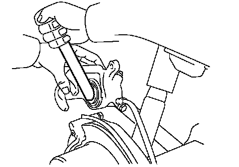
a. Press in the piston with a hammer handle or an equivalent.
HINT:
^ Always change the pads on one wheel at a time as there is a possibility of the opposite piston flying out.
^ If the piston is difficult to push in, loosen the bleeder plug and push in the piston while letting some brake fluid escape.
b. Hold the sliding pin and install the cylinder with the 2 bolts.
Torque: 26 Nm (270 kgf-cm, 20 ft. lbs.)
6. CONNECT REAR FLEXIBLE HOSE
a. Connect the flexible hose with 2 new gaskets and the union bolt.
Torque: 30 Nm (310 kgf-cm, 22 ft. lbs.)
HINT: Install the flexible hose lock securely in the lock hole in the cylinder.
7. FILL RESERVOIR WITH BRAKE FLUID
8. BLEED AIR FROM HYDRAULIC BRAKE BOOSTER
9. BLEED AIR FROM BRAKE LINE
10. CHECK BRAKE FLUID LEVEL IN RESERVOIR
11. CHECK FOR BRAKE FLUID LEAKAGE