Diagnosis System
DIAGNOSIS SYSTEM1. DESCRIPTION
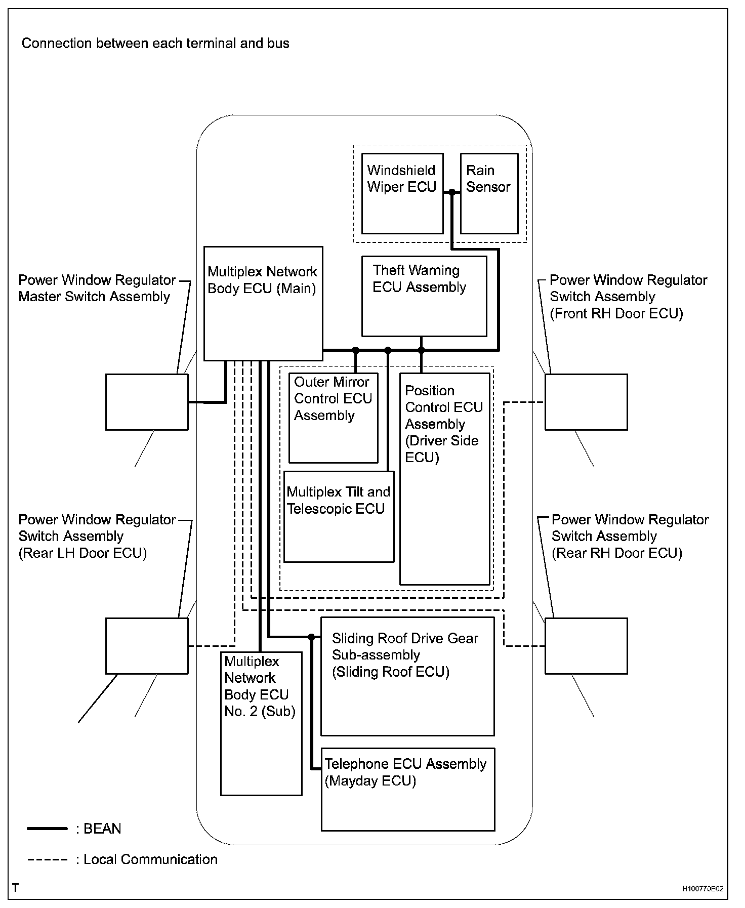
a. As shown in the diagram, all ECUs on this vehicle are connected to each other via communication buses through which various signals are transmitted. These communication buses are diagnosed by the multiplex network body ECU (Main). When the multiplex network body ECU (Main) detects a communication error between ECU, or +B short or GND short of a communication bus, a DTC is output and stored. The multiplex network body ECU (Main) cannot diagnose accurately unless it can function normally. Therefore, first confirm the normal condition by performing the "BASIC INSPECTION" described later, and then, troubleshoot each DTC.
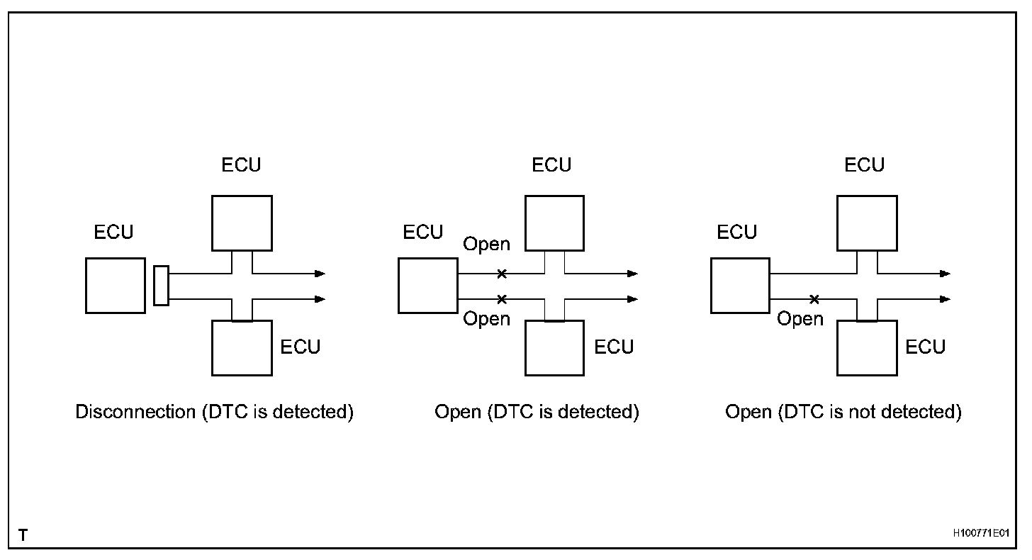
b. If DTC of ECU communication stop is output, connectors may be disconnected, or communication buses may be open at 2 points. It will not become abnormal with only 1 communication bus open.
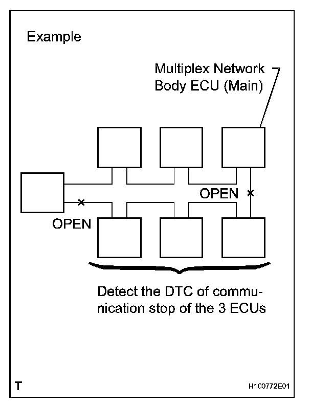
c. If 2 communication buses are open at the position as shown in the illustration, DTC of ECU communication stop between those 2 buses is output.
2. DESCRIPTION
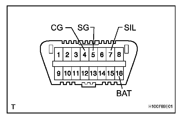
a. Multiplex network body ECU (Main) controls the function of the multiplex communication system of the vehicle. Data of the multiplex communication system and the Diagnostic Trouble Codes (DTC) can be read through the Data Link Connector 3 (DLC3) of the vehicle.