Part 2
4GR-FSE ENGINE MECHANICAL: ENGINE UNIT: INSPECTION
INSPECTION (Continued)
23. REPAIR INTAKE VALVE SEAT
NOTICE:
- Repair the seat while checking the seating position.
- Keep the lip free of foreign matter.

(a) Using a 45° cutter, resurface the valve seat so that the valve seat width is more than the specification.

(b) Using 30° and 75° cutters, correct the valve seat so that the valve contacts the entire circumference of the seat. The contact should be in the center of the valve seat, and the valve seat width should be maintained within the specified range around the entire circumference of the seat.
Width:
1.0 to 1.4 mm (0.039 to 0.055 in.)
(c) Hand rub the valve and valve seat with an abrasive compound.
(d) Check the valve seating position.
24. REPAIR EXHAUST VALVE SEAT
NOTICE:
- Repair the seat while checking the seating position.
- Keep the lip free of foreign matter.

(a) Using a 45° cutter, resurface the valve seat so that the valve seat width is more than the specification.

(b) Using 30° and 60° cutters, correct the valve seat so that the valve contacts the entire circumference of the seat. The contact should be in the center of the valve seat, and the valve seat width should be maintained within the specified range around the entire circumference of the seat.
Width:
1.2 to 1.6 mm (0.047 to 0.063 in.)
(c) Hand rub the valve and valve seat with an abrasive compound.
(d) Check the valve seating position.
25. INSPECT INNER COMPRESSION SPRING

(a) Using vernier calipers, measure the free length of the inner compression spring.
Free length:
57.46 mm (2.2622 in.)
If the free length is not as specified, replace the spring.

(b) Using a steel square, measure the deviation of the inner compression spring.
Maximum deviation:
1.0 mm (0.039 in.)
Maximum angle (reference):
2°
If the deviation is greater than the maximum, replace the spring.
26. INSPECT VALVE GUIDE BUSH OIL CLEARANCE

(a) Using a caliper gauge, measure the inside diameter of the guide bush.
Bush inside diameter:
5.510 to 5.530 mm (0.2169 to 0.2177 in.)
(b) Subtract the valve stem diameter measurement from the guide bush inside diameter measurement.
Standard clearance:

Maximum oil clearance:

For intake side:
If the clearance is greater than the maximum, replace the intake valve and intake guide bush.
For exhaust side:
If the clearance is greater than the maximum, replace the exhaust valve and exhaust guide bush.
27. INSPECT CAMSHAFT THRUST CLEARANCE
(a) Inspect the RH bank camshaft thrust clearance.
(1) Install the RH bank camshafts Reassembly.

(2) Using a dial indicator, measure the thrust clearance while moving the camshaft back and forth.
Standard thrust clearance:
0.08 to 0.13 mm (0.0031 to 0.0051 in.)
Maximum thrust clearance:
0.15 mm (0.006 in.)
If the thrust clearance is greater than the maximum, replace the cylinder head. If the thrust surface is damaged, replace the camshaft.
(b) Inspect the LH bank camshaft thrust clearance.
(1) Install the LH bank camshafts Reassembly.
(2) Using a dial indicator, measure the thrust clearance while moving the camshaft back and forth.
Standard thrust clearance:
0.08 to 0.13 mm (0.0031 to 0.0051 in.)
Maximum thrust clearance:
0.15 mm (0.006 in.)
If the thrust clearance is greater than the maximum, replace the cylinder head. If the thrust surface is damaged, replace the camshaft.
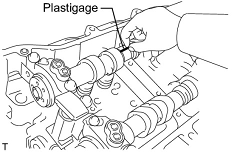
28. INSPECT CAMSHAFT OIL CLEARANCE
(a) Clean the bearing caps, camshaft housing and camshaft journals.
(b) Place the camshafts on the camshaft housing.

(c) Lay a strip of Plastigage across each of the camshaft journals.
(d) Install the bearing caps Reassembly.
NOTE:
Do not turn the camshaft.
(e) Remove the bearing caps Disassembly.

(f) Measure the Plastigage at its widest point.
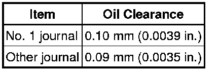
Standard oil clearance:

Maximum oil clearance:

If the oil clearance is greater than the maximum, replace the camshaft. If necessary, replace the camshaft housing.
(g) Clean the bearing caps, camshaft housing and camshaft journals.
(h) Place the camshafts on the camshaft housing.
(i) Lay a strip of Plastigage across each of the camshaft journals.
(j) Install the bearing caps Reassembly.
NOTE:
Do not turn the camshaft.
(k) Remove the bearing caps Disassembly.

(l) Measure the Plastigage at its widest point.
Standard oil clearance:

Maximum oil clearance:
If the oil clearance is greater than the maximum, replace the camshaft. If necessary, replace the camshaft housing.
29. INSPECT CONNECTING ROD THRUST CLEARANCE
(a) Install the connecting rod cap Reassembly.

(b) Using a dial indicator, measure the thrust clearance while moving the connecting rod back and forth.
Standard thrust clearance:
0.25 to 0.40 mm (0.0098 to 0.0157 in.)
Maximum thrust clearance:
0.50 mm (0.020 in.)
If the thrust clearance is greater than the maximum, replace the connecting rod assemblies as necessary. If necessary, replace the crankshaft.
30. INSPECT CONNECTING ROD OIL CLEARANCE
(a) Clean the crank pin and bearing.
(b) Check the crank pin and bearing for pitting and scratches.

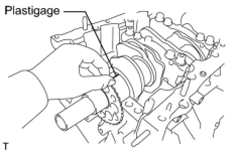
(c) Lay a strip of Plastigage on the crank pin.

(d) Check that the front mark of the connecting rod cap is facing forward.
(e) Install the connecting rod cap Reassembly.
NOTE:
Do not turn the crankshaft.
(f) Remove the 2 bolts and connecting rod cap Disassembly.

(g) Measure the Plastigage at its widest point.
Standard oil clearance:
0.042 to 0.068 mm (0.0017 to 0.0027 in.)
Maximum oil clearance:
0.070 mm (0.0028 in.)
If the oil clearance is greater than the maximum, replace the connecting rod bearings. If necessary, inspect the crankshaft.
HINT:
If replacing a bearing, replace it with one that has the same number as its respective connecting rod cap. Each bearing's standard thickness is indicated by a 1, 2, 3 and 4 mark on its surface.
Connecting rod diameter:

Connecting rod bearing center wall thickness:

Crankshaft pin diameter:
47.992 to 48.000 mm (1.8894 to 1.8898 in.)
(h) Completely remove the Plastigage.
31. INSPECT CRANKSHAFT THRUST CLEARANCE
(a) Install the main bearing cap Reassembly.

(b) Using a dial indicator, measure the thrust clearance while prying the crankshaft back and forth with a screwdriver.
Standard thrust clearance:
0.040 to 0.240 mm (0.00158 to 0.00944 in.)
Maximum thrust clearance:
0.30 mm (0.0118 in.)
If the thrust clearance is greater than the maximum, replace the thrust washers as a set. If necessary, replace the crankshaft.
Thrust washer thickness:
2.43 to 2.48 mm (0.0957 to 0.0976 in.)
32. INSPECT CYLINDER BLOCK FOR WARPAGE

(a) Using a precision straight edge and feeler gauge, measure the warpage of the contact surface of the cylinder head gasket.
Maximum warpage:
0.07 mm (0.0028 in.)
If the warpage is greater than the maximum, replace the cylinder block.
33. INSPECT CYLINDER BORE

(a) Visually check the cylinder for vertical scratches.
If deep scratches are present, rebore all the 6 cylinders. If necessary, replace the cylinder block.

(b) Using a cylinder gauge, measure the cylinder bore diameter at positions A and B in the thrust and axial directions.
Standard diameter:
83.000 to 83.012 mm (3.2677 to 3.2682 in.)
Maximum diameter:
83.200 mm (3.2756 in.)
If the average diameter of 4 positions is greater than the maximum, replace the cylinder block.
34. INSPECT PISTON SUB-ASSEMBLY WITH PIN

(a) Using a micrometer, measure the piston diameter at right angles to the piston center line where the distance from the piston end is as specified.
Distance:
14.3 mm (0.563 in.)
Standard diameter:
82.976 to 82.986 mm (3.2668 to 3.2672 in.)
Maximum diameter:
0.13 mm (0.0051 in.)
35. INSPECT PISTON OIL CLEARANCE
(a) Measure the cylinder bore diameter in the thrust directions.
(b) Subtract the piston diameter measurement from the cylinder bore diameter measurement.
Standard oil clearance:
0.014 to 0.036 mm (0.0006 to 0.0014 in.)
Maximum oil clearance:
0.090 mm (0.0035 in.)
If the oil clearance is greater than the maximum, replace all the pistons. If necessary, replace the cylinder block.
36. INSPECT RING GROOVE CLEARANCE

(a) Using a feeler gauge, measure the clearance between a new piston ring and the wall of the ring groove.
Ring groove clearance:

If the clearance is not as specified, replace the piston.
37. INSPECT PISTON RING END GAP
(a) Insert the piston ring into the cylinder bore.

(b) Using a piston, push the piston ring a little beyond the bottom of the ring travel, 110 mm (4.33 in.) from the top of the cylinder block.

(c) Using a feeler gauge, measure the end gap.
Standard end gap:

Maximum end gap:
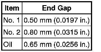
If the end gap is greater than the maximum, replace the piston ring. If the end gap is greater than the maximum even with a new piston ring, rebore all the 6 cylinders or replace the cylinder block.
38. INSPECT PISTON PIN OIL CLEARANCE

(a) Using a caliper gauge, measure the inside diameter of the piston pin hole.
Piston pin hole inside diameter:


(b) Using a micrometer, measure the piston pin diameter.
Piston pin diameter:

(c) Subtract the piston pin diameter measurement from the piston pin hole diameter measurement.
Standard oil clearance:
-0.002 to 0.004 mm (-0.00007 to 0.0001 in.)
Maximum oil clearance:
0.015 mm (0.0006 in.)
If the oil clearance is greater than the maximum, replace the piston and piston pin as a set.

(d) Using a caliper gauge, measure the inside diameter of the connecting rod bushing.
Bushing inside diameter:

(e) Subtract the piston pin diameter measurement from the bushing inside diameter measurement.
Standard oil clearance:
0.005 to 0.011 mm (0.0002 to 0.0004 in.)
Maximum oil clearance:
0.030 mm (0.0012 in.)
If the oil clearance is greater than the maximum, replace the bushing. If necessary, replace the connecting rod and piston pin as a set.
39. INSPECT CONNECTING ROD
(a) Using a rod aligner and feeler gauge, check the connecting rod alignment.

(1) Check for out-of-alignment.
Maximum out-of-alignment:
0.05 mm (0.0020 in.) per 100 mm (3.94 in.)
If the out-of-alignment is greater than the maximum, replace the connecting rod assembly.

(2) Check for twist.
Maximum twist:
0.15 mm (0.0059 in.) per 100 mm (3.94 in.)
If the twist is greater than the maximum, replace the connecting rod assembly.
40. INSPECT CONNECTING ROD BOLT
(a) Using vernier calipers, measure the tension portion diameter of the bolt.
Standard diameter:
7.2 to 7.3 mm (0.284 to 0.287 in.)
Minimum diameter:
7.0 mm (0.276 in.)
If the diameter is less than the minimum, replace the bolt.
41. INSPECT CRANKSHAFT
(a) Inspect for circle runout.
(1) Clean the crank journal.
(2) Place the crankshaft on the V-blocks.

(3) Using a dial indicator, measure the circle runout at the center journal.
Maximum circle runout:
0.06 mm (0.0024 in.)
If the circle runout is greater than the maximum, replace the crankshaft.
(b) Inspect the main journals.

(1) Using a micrometer, measure the diameter of each main journal.
Standard journal diameter:
60.988 to 61.000 mm (2.4011 to 2.4016 in.)
If the diameter is not as specified, check the oil clearance. If necessary, replace the crankshaft.
(2) Check each main journal for taper and out-of-round as shown in the illustration.
Maximum taper and out-of-round:
0.02 mm (0.0008 in.)
If the taper and out-of-round is greater than the maximum, replace the crankshaft.
(c) Inspect the crank pin.

(1) Using a micrometer, measure the diameter of each crank pin.
Crankshaft pin diameter:
47.992 to 48.000 mm (1.8894 to 1.8898 in.)
If the diameter is not as specified, check the oil clearance. If necessary, replace the crankshaft.
(2) Check each crank pin for taper and out-of-round as shown in the illustration.
Maximum taper and out-of-round:
0.02 mm (0.0008 in.)
If the taper and out-of-round is greater than the maximum, replace the crankshaft.
42. INSPECT CRANKSHAFT OIL CLEARANCE
(a) Check the crank journal and bearing for pitting and scratches.
(b) Install the crankshaft bearing Reassembly.
(c) Place the crankshaft on the cylinder block.
(d) Lay a strip of Plastigage across each journal.
(e) Examine the front marks and numbers and install the bearing caps on the cylinder block.
HINT:
A number is marked on each main bearing cap to indicate the installation position.
(f) Install the main bearing cap Reassembly.
NOTE:
Do not turn the crankshaft.
(g) Remove the main bearing caps Disassembly.

(h) Measure the Plastigage at its widest point.
Standard oil clearance:
0.026 to 0.047 mm (0.0010 to 0.0019 in.)
Maximum oil clearance:
0.050 mm (0.0020 in.)
If the oil clearance is greater than the maximum, replace the bearings. If necessary, replace the crankshaft.
NOTE:
Completely remove the Plastigage after the measurement.

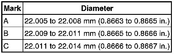
(i) If replacing a bearing, replace it with one having the same number. If the number of the bearing cannot be determined, select the correct bearing by adding together the numbers imprinted on the cylinder block and crankshaft, then refer to the table below for the appropriate bearing number. There are 5 size of standard bearings, marked "1", "2", "3", "4" and "5" accordingly.

HINT:
EXAMPLE: Cylinder block "11" + Crankshaft "06" = Total number 17 (Use bearing "3")
Crankshaft main journal diameter:

Standard upper bearing center wall thickness (No. 1 and No. 4 journal):

Standard lower bearing center wall thickness (No. 1 and No. 4 journal):

Standard upper bearing center wall thickness (No. 2 and No. 3 journal):

Standard lower bearing center wall thickness (No. 2 and No. 3 journal):

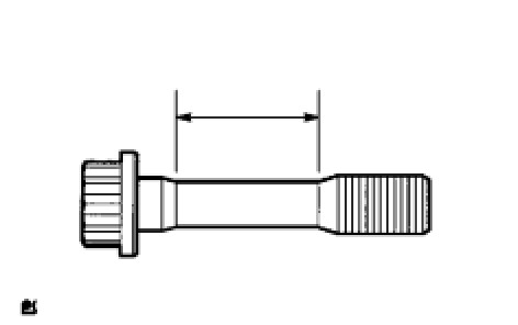
43. INSPECT CRANKSHAFT BEARING CAP SET BOLT

(a) Using vernier calipers, measure the minimum diameter of the compressed thread at the measuring point.
Standard diameter:
10.8 to 11.0 mm (0.4252 to 0.4331 in.)
Minimum diameter:
10.7 mm (0.4213 in.)
Measuring Point:
47 mm (1.85 in.)
If the diameter is less than the minimum, replace the bolt.