P0A78-121 - Drive Motor "A" Inverter Performance
L110 HYBRID VEHICLE CONTROL: HYBRID CONTROL SYSTEM: P0A78-121: Drive Motor "A" Inverter Performance
P0A78-121 - Drive Motor "A" Inverter Performance
DESCRIPTION
For a description of the inverter, P0A78.

INSPECTION PROCEDURE
CAUTION:
- Before inspecting the high-voltage system or disconnecting the low voltage connector of the inverter with converter assembly, take safety precautions such as wearing insulated gloves and removing the service plug grip to prevent electrical shocks. After removing the service plug grip, put it in your pocket to prevent other technicians from accidentally reconnecting it while you are working on the high-voltage system.
- After disconnecting the service plug grip, wait for at least 10 minutes before touching any of the high-voltage connectors or terminals. After waiting, check the voltage at the inspection point in the inverter with converter assembly. The voltage should be 0 V before beginning work.
HINT
Waiting for at least 10 minutes is required to discharge the high-voltage capacitor inside the inverter with converter assembly.
PROCEDURE
1. CHECK DTC OUTPUT (HV)
(a) Connect the Techstream to the DLC3.
(b) Turn the power switch on (IG).
(c) Select the following menu items: Powertrain / Hybrid Control / Trouble Codes.
(d) Check if DTCs are output.
Result:

HINT
P0A78-121 may be set due to a malfunction which also causes DTCs in the table above to be set. In this case, first troubleshoot the output DTCs in the table above. Then, perform a test to attempt to reproduce the problems, and check that no DTCs are output.
YES -- GO TO DTC CHART
NO -- Continue to next step.
2. CHECK CONNECTOR CONNECTION CONDITION (INVERTER WITH CONVERTER ASSEMBLY CONNECTOR)
(a) Turn the power switch off.
(b) Check the connection of the low voltage connector of the inverter with converter assembly.

OK:
The connector is connected securely and there are no contact problems.
NG -- CONNECT SECURELY
OK -- Continue to next step.
3. CHECK HARNESS AND CONNECTOR (INVERTER WITH CONVERTER ASSEMBLY - GENERATOR RESOLVER)
CAUTION:
Be sure to wear insulated gloves.
(a) Turn the power switch off and remove the service plug grip L110 Hybrid Vehicle Control System.
NOTICE:
After removing the service plug grip, do not turn the power switch on (READY), unless instructed by the repair manual because this may cause a malfunction.
(b) Disconnect connector A60 from the inverter with converter assembly.

(c) Turn the power switch on (IG).
(d) Measure the voltage according to the value(s) in the table below.
Standard voltage:

NOTICE:
Turning the power switch on (IG) with the low voltage connector of the inverter with converter assembly disconnected causes other DTCs to be stored. Clear the DTCs after performing this inspection.
NG -- REPAIR OR REPLACE HARNESS OR CONNECTOR
OK -- Continue to next step.
4. CHECK GENERATOR RESOLVER
(a) Turn the power switch off.
(b) Measure the resistance according to the value(s) in the table below.
Standard resistance (Check for open):

(c) Measure the resistance according to the value(s) in the table below.
Standard resistance (Check for short):

NG -- CHECK CONNECTOR CONNECTION CONDITION (GENERATOR RESOLVER CONNECTOR)
OK -- Continue to next step.
5. CHECK HARNESS AND CONNECTOR (INVERTER WITH CONVERTER ASSEMBLY - MOTOR RESOLVER)
(a) Turn the power switch on (IG).

(b) Measure the voltage according to the value(s) in the table below.
Standard voltage:

NOTICE:
Turning the power switch on (IG) with the low voltage connector of the inverter with converter assembly disconnected causes other DTCs to be stored. Clear the DTCs after performing this inspection.
NG -- REPAIR OR REPLACE HARNESS OR CONNECTOR
OK -- Continue to next step.
6. CHECK MOTOR RESOLVER
(a) Turn the power switch off.
(b) Measure the resistance according to the value(s) in the table below.
Standard resistance (Check for open):

(c) Measure the resistance according to the value(s) in the table below.
Standard resistance (Check for short):

NG -- CHECK CONNECTOR CONNECTION CONDITION (MOTOR RESOLVER CONNECTOR)
OK -- Continue to next step.
7. CHECK INVERTER WITH CONVERTER ASSEMBLY (GENERATOR CABLE CONNECTION CONDITION)
(a) Turn the power switch off and remove the service plug grip L110 Hybrid Vehicle Control System.
NOTICE:
After removing the service plug grip, do not turn the power switch on (READY), unless instructed by the repair manual because this may cause a malfunction.
(b) Check for arc marks at the bolts for the generator cable.

(c) Check that the bolts for the generator cable are tightened to the specified torque, the generator cable terminals are connected securely, and there are no contact problems.
NOTICE:
Make sure that the tightening torque of the bolts is between 6.4 and 9.6 N*m (65 and 98 kgf*cm, 57 and 85 in.*lbf).
Torque : 8.0 Nm (82 kgf-cm, 71 in-lbf)
Result:

C -- REPLACE MALFUNCTIONING PARTS
B -- TIGHTEN TO SPECIFIED TORQUE
A -- Continue to next step.
8. CHECK INVERTER WITH CONVERTER ASSEMBLY (MOTOR CABLE CONNECTION CONDITION)
CAUTION:
Be sure to wear insulated gloves.
(a) Check that the service plug grip is not installed.
(b) Check for arc marks at the bolts for the motor cable.

(c) Check that the bolts for the motor cable are tightened to the specified torque, the motor cable terminals are connected securely, and there are no contact problems.
NOTICE:
Make sure that the tightening torque of the bolts is between 6.4 and 9.6 N*m (65 and 98 kgf*cm, 57 and 85 in.*lbf).
Torque : 8.0 Nm (82 kgf-cm, 71 in-lbf)
Result:

C -- REPLACE MALFUNCTIONING PARTS
B -- TIGHTEN TO SPECIFIED TORQUE
A -- Continue to next step.
9. CHECK HYBRID VEHICLE TRANSMISSION ASSEMBLY (MG1)
CAUTION:
Be sure to wear insulated gloves.
(a) Check that the service plug grip is not installed.
(b) Disconnect the generator cable and motor cable from the inverter with converter assembly Service and Repair.
(c) Using a milliohmmeter, measure the resistance according to the value(s) in the table below. (Check MG1 for an interphase short.)

HINT
If the MG1 temperature is high, the resistance varies greatly. Therefore, measure the resistance at least 8 hours after the vehicle is stopped.
Standard resistance:

HINT
- To correct the variation of the measured resistance due to temperature, use the following formula to calculate the resistance at 20°C (68°F).
* R20 = Rt / {1 + 0.00393 X (T - 20)}
- The calculation is based on the following:
* R20: Resistance at 20°C (mOhms)
* Rt: Measured resistance (mOhms)
* T: Temperature when the resistance is measured (°C)
(d) Using a megohmmeter set to 500 V, measure the resistance according to the value(s) in the table below.
NOTICE:
Be sure to set the megohmmeter to 500 V when performing this test. Using a setting higher than 500 V can result in damage to the component being inspected.
Standard resistance:

NG -- CHECK HYBRID VEHICLE TRANSMISSION ASSEMBLY (GENERATOR CABLE CONNECTION CONDITION)
OK -- Continue to next step.
10. CHECK HYBRID VEHICLE TRANSMISSION ASSEMBLY (MG2)
CAUTION:
Be sure to wear insulated gloves.
(a) Check that the service plug grip is not installed.
(b) Disconnect the generator cable and motor cable from the inverter with converter assembly Service and Repair.
(c) Using a milliohmmeter, measure the resistance according to the value(s) in the table below. (Check MG2 for an interphase short.)

HINT
If the MG2 temperature is high, the resistance varies greatly. Therefore, measure the resistance at least 8 hours after the vehicle is stopped.
Standard resistance:

HINT
- To correct the variation of the measured resistance due to temperature, use the following formula to calculate the resistance at 20°C (68°F).
* R20 = Rt / {1 + 0.00393 X (T - 20)}
- The calculation is based on the following:
* R20: Resistance at 20°C (mOhms)
* Rt: Measured resistance (mOhms)
* T: Temperature when the resistance is measured (°C)
(d) Using a megohmmeter set to 500 V, measure the resistance according to the value(s) in the table below.
NOTICE:
Be sure to set the megohmmeter to 500 V when performing this test. Using a setting higher than 500 V can result in damage to the component being inspected.
Standard resistance:

NG -- CHECK HYBRID VEHICLE TRANSMISSION ASSEMBLY (MOTOR CABLE CONNECTION CONDITION)
OK -- Continue to next step.
11. CHECK CONNECTOR CONNECTION CONDITION (GENERATOR RESOLVER CONNECTOR)
(a) Check the connection of the generator resolver connector.

Result:
The connector is connected securely and there are no contact problems.
NG -- CONNECT SECURELY
OK -- Continue to next step.
12. CHECK CONNECTOR CONNECTION CONDITION (MOTOR RESOLVER CONNECTOR)
(a) Check the connection of the motor resolver connector.

Result:
The connector is connected securely and there are no contact problems.
NG -- CONNECT SECURELY
OK -- Continue to next step.
13. CHECK INVERTER WITH CONVERTER ASSEMBLY (HIGH VOLTAGE CONNECTOR CONNECTION CONDITION)
CAUTION:
Be sure to wear insulated gloves.
(a) Check that the service plug grip is not installed.
(b) Check for arc marks at the bolts for the high voltage connector.
(c) Check the connection of the high voltage connector of the inverter with converter assembly.

Result:

C -- REPLACE MALFUNCTIONING PARTS
B -- CONNECT SECURELY
A -- Continue to next step.
14. CHECK SERVICE PLUG GRIP
CAUTION:
Be sure to wear insulated gloves.
(a) Check the connection of the service plug grip.
OK:
Dirt or foreign objects have not entered the connection, or there is no evidence of contamination.
NG -- REPLACE SERVICE PLUG GRIP
OK -- Continue to next step.
15. CHECK ELECTRIC VEHICLE FUSE
(a) Measure the resistance according to the value(s) in the table below.

Standard resistance:

NG -- REPLACE ELECTRIC VEHICLE FUSE
OK -- Continue to next step.
16. CHECK FRAME WIRE
CAUTION:
Be sure to wear insulated gloves.
(a) Check that the service plug grip is not installed.
(b) Disconnect the frame wire from the HV relay Components.

(c) Disconnect the frame wire from the high voltage connector of the inverter with converter assembly Service and Repair.
(d) Using a megohmmeter set to 500 V, measure the resistance according to the value(s) in the table below.

NOTICE:
Be sure to set the megohmmeter to 500 V when performing this test. Using a setting higher than 500 V can result in damage to the component being inspected.
Standard resistance:

(e) Measure the resistance according to the value(s) in the table below.

Standard resistance:

NG -- REPLACE FRAME WIRE
OK -- Continue to next step.
17. INSPECT HV RELAY ASSEMBLY (SMRB)
CAUTION:
Be sure to wear insulated gloves.
(a) Check that the service plug grip is not installed.
(b) Remove the HV relay assembly from the vehicle Components.
(c) Measure the resistance according to the value(s) in the table below.
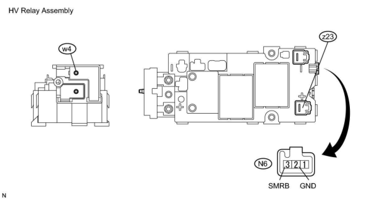
Standard resistance:

(d) Measure the resistance according to the value(s) in the table below.
Standard resistance:

NG -- REPLACE HV RELAY ASSEMBLY Components
OK -- Continue to next step.
18. INSPECT HV RELAY ASSEMBLY (SMRG)
CAUTION:
Be sure to wear insulated gloves.
(a) Check that the service plug grip is not installed.
(b) Measure the resistance according to the value(s) in the table below.
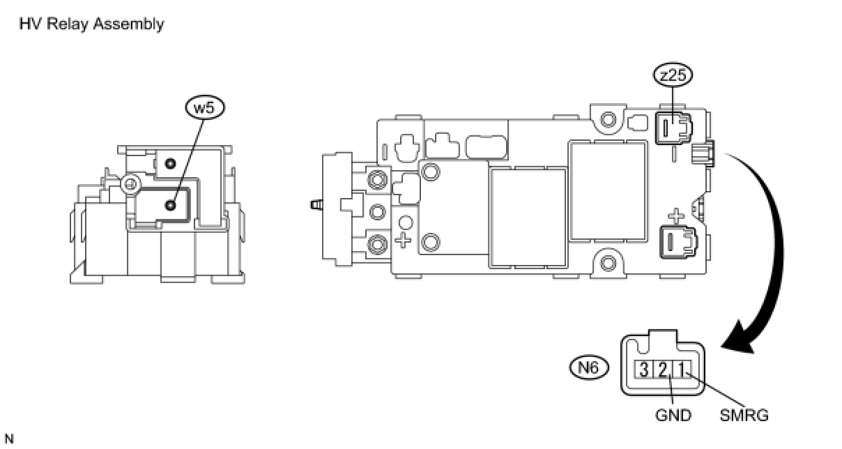
Standard resistance:

(c) Measure the resistance according to the value(s) in the table below.
Standard resistance:

NG -- REPLACE HV RELAY ASSEMBLY Components
OK -- REPLACE INVERTER WITH CONVERTER ASSEMBLY Service and Repair
19. CHECK CONNECTOR CONNECTION CONDITION (MOTOR RESOLVER CONNECTOR)
(a) Check the connection of the motor resolver connector.
Result:
The connector is connected securely and there are no contact problems.
NG -- CONNECT SECURELY
OK -- Continue to next step.
20. CHECK HARNESS AND CONNECTOR (INVERTER WITH CONVERTER ASSEMBLY - MOTOR RESOLVER)
(a) Disconnect connector E88 from the motor resolver.

(b) Measure the resistance according to the value(s) in the table below.
Standard resistance (Check for open):

Standard resistance (Check for short):

HINT
The motor resolver is not available separately. If it requires replacement, replace the hybrid vehicle transmission assembly.
NG -- REPAIR OR REPLACE HARNESS OR CONNECTOR
OK -- REPLACE HYBRID VEHICLE TRANSMISSION ASSEMBLY Components
21. CHECK CONNECTOR CONNECTION CONDITION (GENERATOR RESOLVER CONNECTOR)
(a) Check the connection of the generator resolver connector.
Result:
The connector is connected securely and there are no contact problems.
NG -- CONNECT SECURELY
OK -- Continue to next step.
22. CHECK HARNESS AND CONNECTOR (INVERTER WITH CONVERTER ASSEMBLY - GENERATOR RESOLVER)
(a) Disconnect connector E87 from the generator resolver.

(b) Measure the resistance according to the value(s) in the table below.
Standard resistance (Check for open):

Standard resistance (Check for short):

HINT
The generator resolver is not available separately. If it requires replacement, replace the hybrid vehicle transmission assembly.
NG -- REPAIR OR REPLACE HARNESS OR CONNECTOR
OK -- REPLACE HYBRID VEHICLE TRANSMISSION ASSEMBLY Components
23. CHECK HYBRID VEHICLE TRANSMISSION ASSEMBLY (GENERATOR CABLE CONNECTION CONDITION)
CAUTION:
Be sure to wear insulated gloves.
(a) Turn the power switch off and remove the service plug grip L110 Hybrid Vehicle Control System.
NOTICE:
After removing the service plug grip, do not turn the power switch on (READY), unless instructed by the repair manual because this may cause a malfunction.
(b) Remove the hybrid vehicle transmission assembly Components.

(c) Check for arc marks at the bolts for the generator cable.
(d) Check that the bolts for the generator cable are tightened to the specified torque, the generator cable terminals are connected securely, and there are no contact problems.
NOTICE:
Make sure that the tightening torque of the bolts is between 6.4 and 9.6 N*m (65 and 98 kgf*cm, 57 and 85 in.*lbf).
Torque : 8.0 Nm (82 kgf-cm, 71 in-lbf)
Result:

C -- REPLACE MALFUNCTIONING PARTS
B -- CONNECT SECURELY
A -- Continue to next step.
24. CHECK GENERATOR CABLE
CAUTION:
Be sure to wear insulated gloves.
(a) Check that the service plug grip is not installed.
(b) Remove the generator cable from the transmission Components.
(c) Using a megohmmeter set to 500 V, measure the resistance according to the value(s) in the table below.

NOTICE:
Be sure to set the megohmmeter to 500 V when performing this test. Using a setting higher than 500 V can result in damage to the component being inspected.
Standard resistance:

(d) Measure the resistance of each conductor in the generator cable according to the value(s) in the table below.
Standard resistance:

NG -- REPLACE GENERATOR CABLE
OK -- REPLACE HYBRID VEHICLE TRANSMISSION ASSEMBLY Components
25. CHECK HYBRID VEHICLE TRANSMISSION ASSEMBLY (MOTOR CABLE CONNECTION CONDITION)
CAUTION:
Be sure to wear insulated gloves.
(a) Turn the power switch off and remove the service plug grip L110 Hybrid Vehicle Control System.
NOTICE:
After removing the service plug grip, do not turn the power switch on (READY), unless instructed by the repair manual because this may cause a malfunction.
(b) Remove the hybrid vehicle transmission assembly Components.

(c) Check for arc marks at the bolts for the motor cable.
(d) Check that the bolts for the motor cable are tightened to the specified torque, the motor cable terminals are connected securely, and there are no contact problems.
NOTICE:
Make sure that the tightening torque of the bolts is between 6.4 and 9.6 N*m (65 and 98 kgf*cm, 57 and 85 in.*lbf).
Torque : 8.0 Nm (82 kgf-cm, 71 in-lbf)
Result:

C -- REPLACE MALFUNCTIONING PARTS
B -- CONNECT SECURELY
A -- Continue to next step.
26. CHECK MOTOR CABLE
CAUTION:
Be sure to wear insulated gloves.
(a) Check that the service plug grip is not installed.
(b) Remove the motor cable from the transmission Components.
(c) Using a megohmmeter set to 500 V, measure the resistance according to the value(s) in the table below.

NOTICE:
Be sure to set the megohmmeter to 500 V when performing this test. Using a setting higher than 500 V can result in damage to the component being inspected.
Standard resistance:

(d) Measure the resistance of each conductor in the motor cable according to the value(s) in the table below.
Standard resistance:

NG -- REPLACE MOTOR CABLE
OK -- REPLACE HYBRID VEHICLE TRANSMISSION ASSEMBLY Components