Part 1
AUDIO / VISUAL: AUDIO AND VISUAL SYSTEM (w/ Navigation System): Speaker Circuit
- Speaker Circuit
DESCRIPTION
If there is a short in a speaker circuit, the stereo component amplifier assembly detects the short and stops output to the speakers.
Thus sound cannot be heard from the speakers even if there is no malfunction in the stereo component amplifier assembly, DCM (telematics transceiver)*1 or speakers.
* *1: w/ Manual (SOS) Switch
WIRING DIAGRAM
1. w/o Front Center Speaker


2. w/ Front Center Speaker


INSPECTION PROCEDURE
PROCEDURE
1. CONFIRM MODEL
(a) Choose the model to be inspected.
Result:

B -- CHECK HARNESS AND CONNECTOR
A -- Continue to next step.
2. CHECK HARNESS AND CONNECTOR
(a) Disconnect the connectors from the stereo component amplifier assembly, DCM (telematics transceiver) (w/ Manual (SOS) Switch) and speakers.
(b) Measure the resistance between the front No. 1 speaker LH and the stereo component amplifier assembly to check for an open circuit in the wire harness.
Standard Resistance:

(c) w/o Manual (SOS) Switch:
Measure the resistance between the front No. 1 speaker RH and the stereo component amplifier assembly to check for an open circuit in the wire harness.
Standard Resistance:

(d) w/ Manual (SOS) Switch:
Measure the resistance between the stereo component amplifier assembly and the DCM (telematics transceiver) to check for an open circuit in the wire harness.
Standard Resistance:

(e) w/ Manual (SOS) Switch:
Measure the resistance between the front No. 1 speaker RH and the DCM (telematics transceiver) to check for an open circuit in the wire harness.
Standard Resistance:

(f) Measure the resistance between each of the front No. 3 speakers and the stereo component amplifier assembly to check for an open circuit in the wire harness.
Standard Resistance:

(g) Measure the resistance between each of the front No. 2 speakers and the front No. 3 speakers to check for an open circuit in the wire harness.
Standard Resistance:

(h) Measure the resistance between each of the rear speakers and the stereo component amplifier assembly to check for an open circuit in the wire harness.
Standard Resistance:

(i) Measure the resistance between each of the rear No. 3 speakers and the stereo component amplifier assembly to check for an open circuit in the wire harness.
Standard Resistance:

(j) Measure the resistance between each of the rear No. 2 speakers and the rear No. 3 speakers to check for an open circuit in the wire harness.
Standard Resistance:

(k) Measure the resistance between the stereo component speaker and the stereo component amplifier assembly to check for an open circuit in the wire harness.
Standard Resistance:

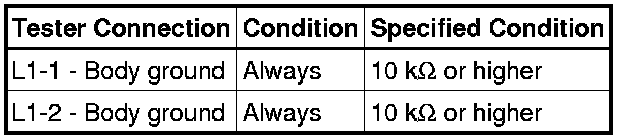
(l) Measure the resistance between the stereo component amplifier assembly and body ground to check for a short circuit in the wire harness.
Standard Resistance:

(m) w/ Manual (SOS) Switch:
Measure the resistance between the front No. 1 speaker RH and body ground to check for a short circuit in the wire harness.
Standard Resistance:
(n) Measure the resistance between each of the front No. 2 speakers and body ground to check for a short circuit in the wire harness.
Standard Resistance:

(o) Measure the resistance between each of the rear No. 2 speakers and body ground to check for a short circuit in the wire harness.
Standard Resistance:

(p) Proceed to the next step based on the inspection result.
Result:

B -- INSPECT FRONT NO. 1 SPEAKER
A -- REPAIR OR REPLACE HARNESS OR CONNECTOR
3. CHECK HARNESS AND CONNECTOR
(a) Disconnect the connectors from the stereo component amplifier assembly, DCM (telematics transceiver)*1 and speakers.
*1: w/ Manual (SOS) Switch
(b) Measure the resistance between the front No. 1 speaker LH and the stereo component amplifier assembly to check for an open circuit in the wire harness.
Standard Resistance:

(c) w/o Manual (SOS) Switch:
Measure the resistance between the front No. 1 speaker RH and the stereo component amplifier assembly to check for an open circuit in the wire harness.
Standard Resistance:

(d) w/ Manual (SOS) Switch:
Measure the resistance between the stereo component amplifier assembly and the DCM (telematics transceiver) to check for an open circuit in the wire harness.
Standard Resistance:

(e) w/ Manual (SOS) Switch:
Measure the resistance between the front No. 1 speaker RH and the DCM (telematics transceiver) to check for an open circuit in the wire harness.
Standard Resistance:

(f) Measure the resistance between each of the front No. 3 speakers and the stereo component amplifier assembly to check for an open circuit in the wire harness.
Standard Resistance:

(g) Measure the resistance between each of the front No. 2 speakers and the front No. 3 speakers to check for an open circuit in the wire harness.
Standard Resistance:

(h) Measure the resistance between each of the rear No. 2 speakers and the stereo component amplifier assembly to check for an open circuit in the wire harness.
Standard Resistance:

(i) Measure the resistance between each of the rear speakers and the rear No. 2 speakers to check for an open circuit in the wire harness.
Standard Resistance:

(j) Measure the resistance between the stereo component speaker and the stereo component amplifier assembly to check for an open circuit in the wire harness.
Standard Resistance:

(k) Measure the resistance between each of the rear stereo component speakers and the stereo component amplifier assembly to check for an open circuit in the wire harness.
Standard Resistance:

(l) Measure the resistance between the front stereo component speaker and the stereo component amplifier assembly to check for an open circuit in the wire harness.
Standard Resistance:

(m) Measure the resistance between the stereo component amplifier assembly and body ground to check for a short circuit in the wire harness.
Standard Resistance:

(n) w/ Manual (SOS) Switch:
Measure the resistance between the front No. 1 speaker RH and body ground to check for a short circuit in the wire harness.
Standard Resistance:

(o) Measure the resistance between each of the front No. 2 speakers and body ground to check for a short circuit in the wire harness.
Standard Resistance:

(p) Measure the resistance between each of the rear speakers and body ground to check for a short circuit in the wire harness.
Standard Resistance:

NG -- REPAIR OR REPLACE HARNESS OR CONNECTOR
OK -- Continue to next step.