Part 2
4GR-FSE ENGINE MECHANICAL: ENGINE UNIT: DISASSEMBLY
39. REMOVE CAMSHAFT TIMING GEARS AND NO. 2 CHAIN (for Bank 1)
(a) While raising the No. 2 chain tensioner, insert a pin of dia 1.0 mm (0.039 in.) into the hole to fix the No. 2 chain tensioner.

(b) Using SST to hold the hexagonal portion of each camshaft, loosen the flange bolts of the camshaft timing gear assembly and the camshaft timing exhaust gear assembly RH.

SST : 09922-10010
NOTICE:
* Be careful not to damage the cylinder head with SST.
* Do not loosen the other bolts. If any of the bolts is loosened, replace the camshaft timing gear assembly and/or the camshaft timing exhaust gear assembly with a new one.
(c) Remove the No. 2 chain.
40. REMOVE NO. 2 CHAIN TENSIONER ASSEMBLY
(a) Remove the bolt and No. 2 chain tensioner.

41. REMOVE CAMSHAFT BEARING CAP (for Bank 1)
(a) Check that the camshafts are positioned as shown in the illustration.

(b) Uniformly loosen and remove the 9 bearing cap bolts in the sequence shown in the illustration.

(c) Uniformly loosen and remove the 14 bearing cap bolts in the sequence shown in the illustration.

NOTICE:
Uniformly loosen the bolts while keeping the camshaft level.
(d) Remove the 6 bearing caps.
42. REMOVE CAMSHAFT
(a) Remove the camshaft.
43. REMOVE NO. 2 CAMSHAFT
(a) Remove the No. 2 camshaft.
44. REMOVE CAMSHAFT HOUSING SUB-ASSEMBLY RH
(a) Remove the camshaft housing sub-assembly RH by prying between the cylinder head and camshaft housing sub-assembly RH with a screwdriver.

NOTICE:
Be careful not to damage the contact surfaces of the cylinder head and camshaft housing.
HINT
Tape the screwdriver tip before use.
45. REMOVE CAMSHAFT TIMING GEARS AND NO. 2 CHAIN (for Bank 2)
(a) While pushing down the No. 3 chain tensioner, insert a pin of dia 1.0 mm (0.039 in.) into the hole to fix the No. 3 chain tensioner.

(b) Using SST to hold the hexagonal portion of each camshaft, loosen the flange bolts of the camshaft timing gear assembly and the camshaft timing exhaust gear assembly LH.

SST : 09922-10010
NOTICE:
* Be careful not to damage the cylinder head with SST.
* Do not loosen the other bolts. If any of the bolts is loosened, replace the camshaft timing gear assembly and/or the camshaft timing exhaust gear assembly with a new one.
(c) Remove the No. 2 chain.
46. REMOVE NO. 3 CHAIN TENSIONER ASSEMBLY
(a) Remove the bolt and No. 3 chain tensioner.

47. REMOVE CAMSHAFT BEARING CAP (for Bank 2)
(a) Check that the camshafts are positioned as shown in the illustration.

(b) Uniformly loosen and remove the 8 bearing cap bolts in the sequence shown in the illustration.

(c) Uniformly loosen and remove the 13 bearing cap bolts in the sequence shown in the illustration.

NOTICE:
Uniformly loosen the bolts while keeping the camshaft level.
(d) Remove the 5 bearing caps.
48. REMOVE NO. 3 CAMSHAFT
(a) Remove the No. 3 camshaft.
49. REMOVE NO. 4 CAMSHAFT
(a) Remove the No. 4 camshaft.
50. REMOVE CAMSHAFT HOUSING SUB-ASSEMBLY LH
(a) Remove the camshaft housing by prying between the cylinder head and camshaft housing with a screwdriver.

NOTICE:
Be careful not to damage the contact surfaces of the cylinder head and camshaft housing.
HINT
Tape the screwdriver tip before use.
51. REMOVE NO. 1 VALVE ROCKER ARM SUB-ASSEMBLY
(a) Remove the 24 valve rocker arms.

HINT
Arrange the removed parts in the correct order.
52. REMOVE VALVE LASH ADJUSTER ASSEMBLY
(a) Remove the 24 valve lash adjusters from the cylinder head.
HINT
Arrange the removed parts in the correct order.
53. REMOVE CYLINDER HEAD SUB-ASSEMBLY RH
(a) Using a 10 mm bi-hexagon wrench, uniformly loosen the 8 bolts in the sequence shown in the illustration. Remove the 8 cylinder head bolts and plate washers.

NOTICE:
* Be careful not to drop washers into the cylinder head.
* Cylinder head warpage or cracking could result from removing bolts in an incorrect order.
HINT
Be sure to keep separate the removed parts for each installation position.
(b) Remove the cylinder head and gasket.
54. REMOVE CYLINDER HEAD SUB-ASSEMBLY LH
(a) Uniformly loosen and remove the bolts in the sequence shown in the illustration.

(b) Using a 10 mm bi-hexagon wrench, uniformly loosen the 8 bolts in the sequence shown in the illustration. Remove the 8 cylinder head bolts and plate washers.

NOTICE:
* Be careful not to drop washers into the cylinder head.
* Cylinder head warpage or cracking could result from removing bolts in an incorrect order.
HINT
Be sure to keep separate the removed parts for each installation position.
(c) Remove the cylinder head and gasket.
55. REMOVE CYLINDER BLOCK WATER JACKET SPACER RH
(a) Using needle-nose pliers, remove the cylinder block water jacket spacer RH.
NOTICE:
Be sure to remove the water jacket spacer if turning the cylinder block.
56. REMOVE CYLINDER BLOCK WATER JACKET SPACER LH
(a) Using needle-nose pliers, remove the cylinder block water jacket spacer LH.
NOTICE:
Be sure to remove the water jacket spacer if turning the cylinder block.
57. REMOVE KNOCK SENSOR
(a) Disconnect the knock sensor wire.

(b) Disconnect the 2 knock sensor connectors.
(c) Remove the 2 bolts and knock sensors.

58. REMOVE WATER OUTLET PIPE SUB-ASSEMBLY
(a) Remove the 2 bolts and water outlet pipe.

59. REMOVE VALVE STEM CAP
(a) Remove the valve stem caps from the cylinder heads.
HINT
Arrange the removed parts in the correct order.
60. REMOVE INTAKE VALVE
(a) Using SST, compress the compression spring and remove the valve spring retainer locks.

SST : 09202-70020
09202-00010
(b) Remove the retainer, compression spring and valve.
HINT
Arrange the removed parts in the correct order.
61. REMOVE EXHAUST VALVE
(a) Using SST, compress the compression spring and remove the valve spring retainer locks.

SST : 09202-70020
09202-00010
(b) Remove the retainer, compression spring and valve.
HINT
Arrange the removed parts in the correct order.
62. REMOVE VALVE STEM OIL SEAL
(a) Using needle-nose pliers, remove the oil seals.

63. REMOVE VALVE SPRING SEAT
(a) Using compressed air and a magnetic finger, remove the valve spring seats by blowing air onto them.

64. REMOVE NO. 1 STRAIGHT SCREW PLUG
(a) Using a 10 mm hexagon wrench, remove the 4 screw plugs and 4 gaskets.

NOTICE:
If water leaks from the straight screw plug or the plug corrodes, replace it.
65. REMOVE NO. 2 STRAIGHT SCREW PLUG
(a) Using a 14 mm hexagon wrench, remove the screw plugs and gaskets.

NOTICE:
If water leaks from the straight screw plug or the plug corrodes, replace it.
66. REMOVE UNION
(a) Remove the unions from the cylinder heads.
67. REMOVE RING PIN
NOTICE:
It is not necessary to remove the ring pin unless it is being replaced.
68. REMOVE STUD BOLT
NOTICE:
If the stud bolt is deformed or the threads are damaged, replace it.
69. REMOVE INTAKE VALVE GUIDE BUSH
(a) Heat the cylinder head to 80 to 100°C (176 to 212°F).
(b) Place the cylinder head on wooden blocks.
(c) Using SST and a hammer, tap out the guide bushes.

SST : 09201-10000
09201-01050
SST : 09950-70010
09951-07100
70. REMOVE EXHAUST VALVE GUIDE BUSH
(a) Heat the cylinder head to 80 to 100°C (176 to 212°F).
(b) Place the cylinder head on wooden blocks.
(c) Using SST and a hammer, tap out the guide bushes.

SST : 09201-10000
09201-01050
SST : 09950-70010
09951-07100
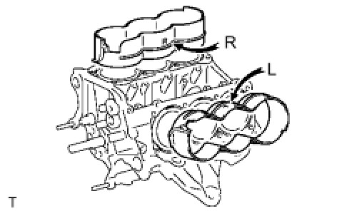
71. REMOVE PISTON SUB-ASSEMBLY WITH CONNECTING ROD
(a) Check that the matchmarks on the connecting rod and cap are aligned.
HINT
The matchmarks on the connecting rods and caps are for ensuring the correct reassembly.
(b) Remove the 2 connecting rod cap bolts.
(c) Using the 2 removed connecting rod caps bolts, remove the connecting rod cap and lower bearing by wiggling the connecting rod cap right and left.
HINT
Keep the lower bearing inserted to the connecting rod cap.
(d) Using a ridge reamer, remove all the carbon from the top of the cylinder.

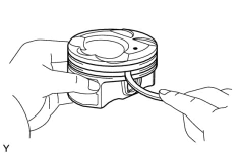
(e) Push the piston, connecting rod assembly and upper bearing through the top of the cylinder block.
HINT
* Keep the bearing, connecting rod and cap together.
* Arrange the piston and connecting rod assemblies in the correct order.
72. REMOVE CONNECTING ROD BEARING
NOTICE:
Arrange the removed parts in the correct order.
73. REMOVE CRANKSHAFT
(a) Uniformly loosen and remove the 8 main bearing cap bolts and seal washers in the several steps and in the sequence shown in the illustration.

(b) Uniformly loosen the 16 bearing cap bolts, in several steps, in the sequence shown in the illustration.

(c) Using a screwdriver, pry out the main bearing caps. Remove the 4 main bearing caps and lower bearings.

NOTICE:
* Push up on the cap little by little, from the right and left side alternately until the cap can be removed.
* Be careful not to damage the joint surface of the cylinder block and the main bearing cap.
(d) Remove the crankshaft.
74. REMOVE CRANKSHAFT BEARING
HINT
Arrange the removed parts in the correct order.
75. REMOVE CRANKSHAFT THRUST WASHER SET
(a) Remove the upper bearings and upper thrust washers from the cylinder block.

76. REMOVE PISTON RING SET
(a) Using a piston ring expander, remove the 2 compression rings.

(b) Using a piston ring expander, remove the oil ring rail.
(c) Remove the oil ring expander by hand.
HINT
Arrange the removed parts in the correct order.
77. REMOVE PISTON SUB-ASSEMBLY WITH PIN
(a) Disconnect the connecting rod from the piston.

(1) Using a screwdriver, pry off the snap rings from the piston.
(2) Gradually heat the piston to approximately 80°C (176°F).

(3) Using a brass bar and plastic hammer, lightly tap out the piston pin and remove the connecting rod.

HINT
* The piston and pin are a matched set.
* Arrange the pistons, pins, rings, connecting rods and bearings in the correct order.
(b) Using a gasket scraper, remove the carbon from the piston top.

(c) Using a groove cleaning tool or broken ring, clean the piston ring grooves.
(d) Using solvent and a brush, thoroughly clean the piston.

NOTICE:
Do not use a wire brush.
78. REMOVE NO. 1 OIL NOZZLE SUB-ASSEMBLY
(a) Using a 5 mm hexagon wrench, remove the bolts and oil nozzles.

(b) Check the 3 oil nozzles for damage or clogging.
79. REMOVE CONNECTING ROD SMALL END BUSH
(a) Using SST and press, press out the bush.

SST : 09222-30010