Steering Lock Motor Drive Power Circuit
STEERING COLUMN: STEERING LOCK SYSTEM: Steering Lock Motor Drive Power Circuit
- Steering Lock Motor Drive Power Circuit
DESCRIPTION
The steering lock ECU is connected to the main body ECU and certification ECU. The steering lock ECU cannot activate the motor unless it receives permission signals from both ECUs. (The main body ECU permits the steering lock ECU to supply power to activate the motor.)
WIRING DIAGRAM

INSPECTION PROCEDURE
PROCEDURE
1. CHECK VEHICLE CONDITION
(a) Check the problem symptom of the steering lock system.
Result:
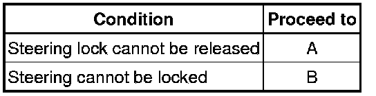
B -- INSPECT STEERING LOCK ACTUATOR ASSEMBLY (STEERING LOCK ECU)
A -- Continue to next step.
2. READ VALUE USING TECHSTREAM
(a) Connect Techstream to the DLC3.
(b) Turn the engine switch on (IG).
(c) Turn Techstream on.
(d) Read the DATA LIST. Enter the following menus: Body / Smart Access / Data List.
Smart Access:
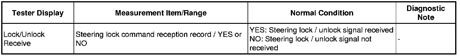
(e) Check if a steering unlock command signal has been received.
OK:
"YES" is displayed on the tester display.
NG -- CHECK SMART ACCESS SYSTEM WITH PUSH-BUTTON START
OK -- Continue to next step.
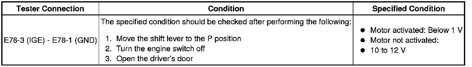
3. INSPECT STEERING LOCK ACTUATOR ASSEMBLY (STEERING LOCK ECU)
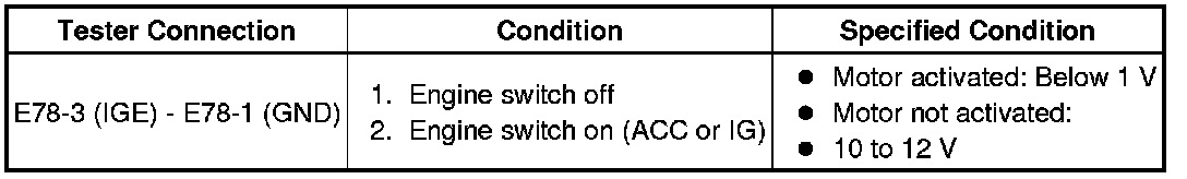
(a) Measure the voltage according to the value(s) in the table below.

Standard voltage:
OK -- PROCEED TO NEXT CIRCUIT INSPECTION SHOWN IN PROBLEM SYMPTOMS TABLE
NG -- Continue to next step.
4. CHECK HARNESS AND CONNECTOR (STEERING LOCK ACTUATOR ASSEMBLY - BODY GROUND)
(a) Disconnect the E78 connector from the steering lock actuator assembly.

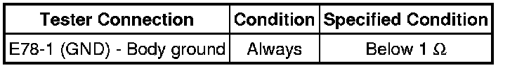
(b) Measure the resistance according to the value(s) in the table below.
Standard resistance:
NG -- REPAIR OR REPLACE HARNESS OR CONNECTOR
OK -- Continue to next step.
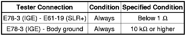
5. CHECK HARNESS AND CONNECTOR (STEERING LOCK ACTUATOR ASSEMBLY - MAIN BODY ECU)
(a) Disconnect the E61 connector from the main body ECU.

(b) Measure the resistance according to the value(s) in the table below.
Standard resistance:

NG -- REPAIR OR REPLACE HARNESS OR CONNECTOR
OK -- REPLACE MAIN BODY ECU
6. INSPECT STEERING LOCK ACTUATOR ASSEMBLY (STEERING LOCK ECU)
(a) Measure the voltage according to the value(s) in the table below.
Standard voltage:
OK -- PROCEED TO NEXT CIRCUIT INSPECTION SHOWN IN PROBLEM SYMPTOMS TABLE
NG -- Continue to next step.
7. CHECK HARNESS AND CONNECTOR (STEERING LOCK ACTUATOR ASSEMBLY - MAIN BODY ECU)
(a) Disconnect the E78 connector from the steering lock actuator assembly.
(b) Disconnect the E61 connector from the main body ECU.
(c) Measure the resistance according to the value(s) in the table below.
Standard resistance:
NG -- REPAIR OR REPLACE HARNESS OR CONNECTOR
OK -- REPLACE MAIN BODY ECU