Disassembly
DISASSEMBLE1. Mount transmission in suitable holding fixture.
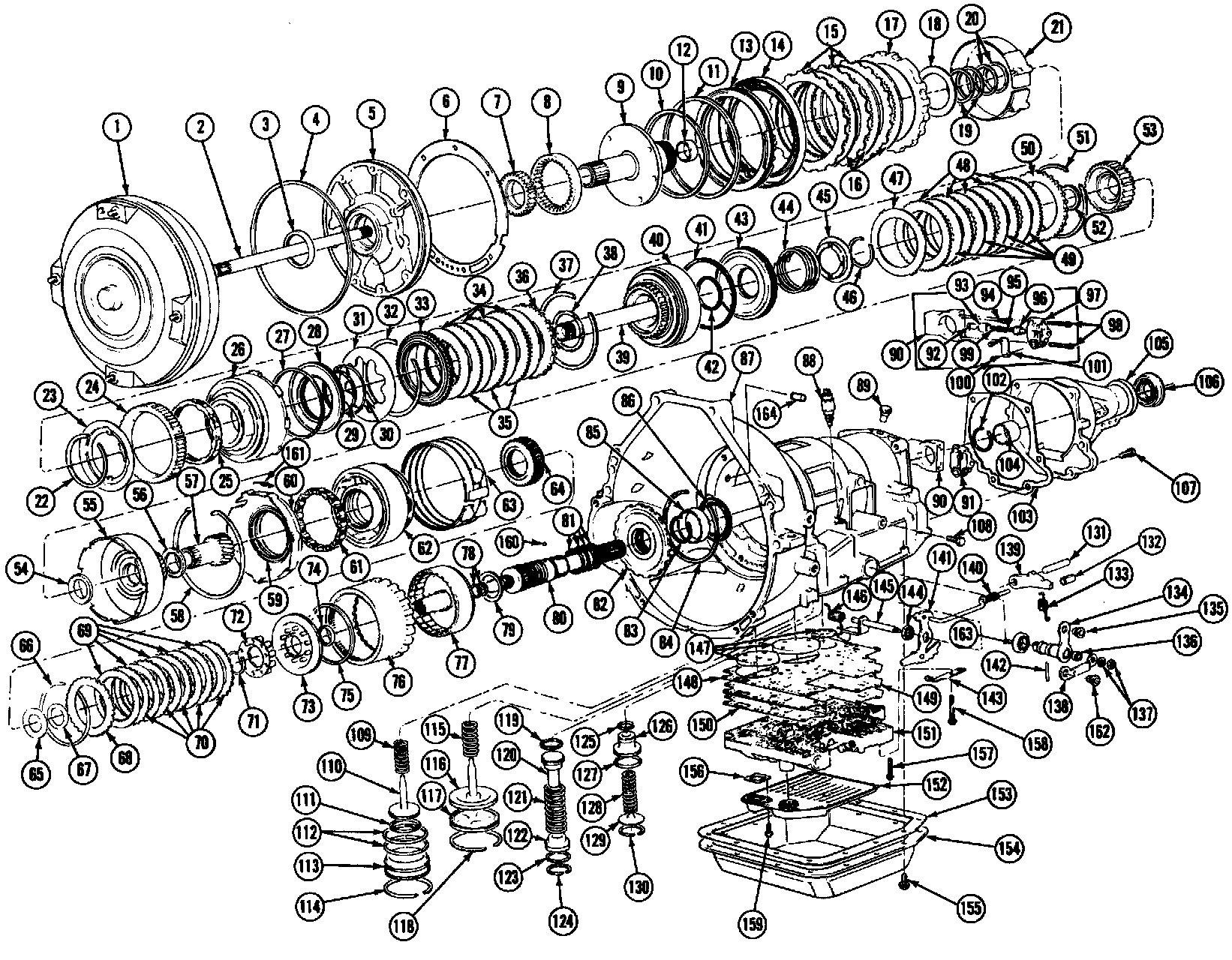
Exploded View Of Ford Automatic Overdrive Transmission, (Part 1 Of 3). 2 Wheel Drive Shown, 4 Wheel Drive Similar:
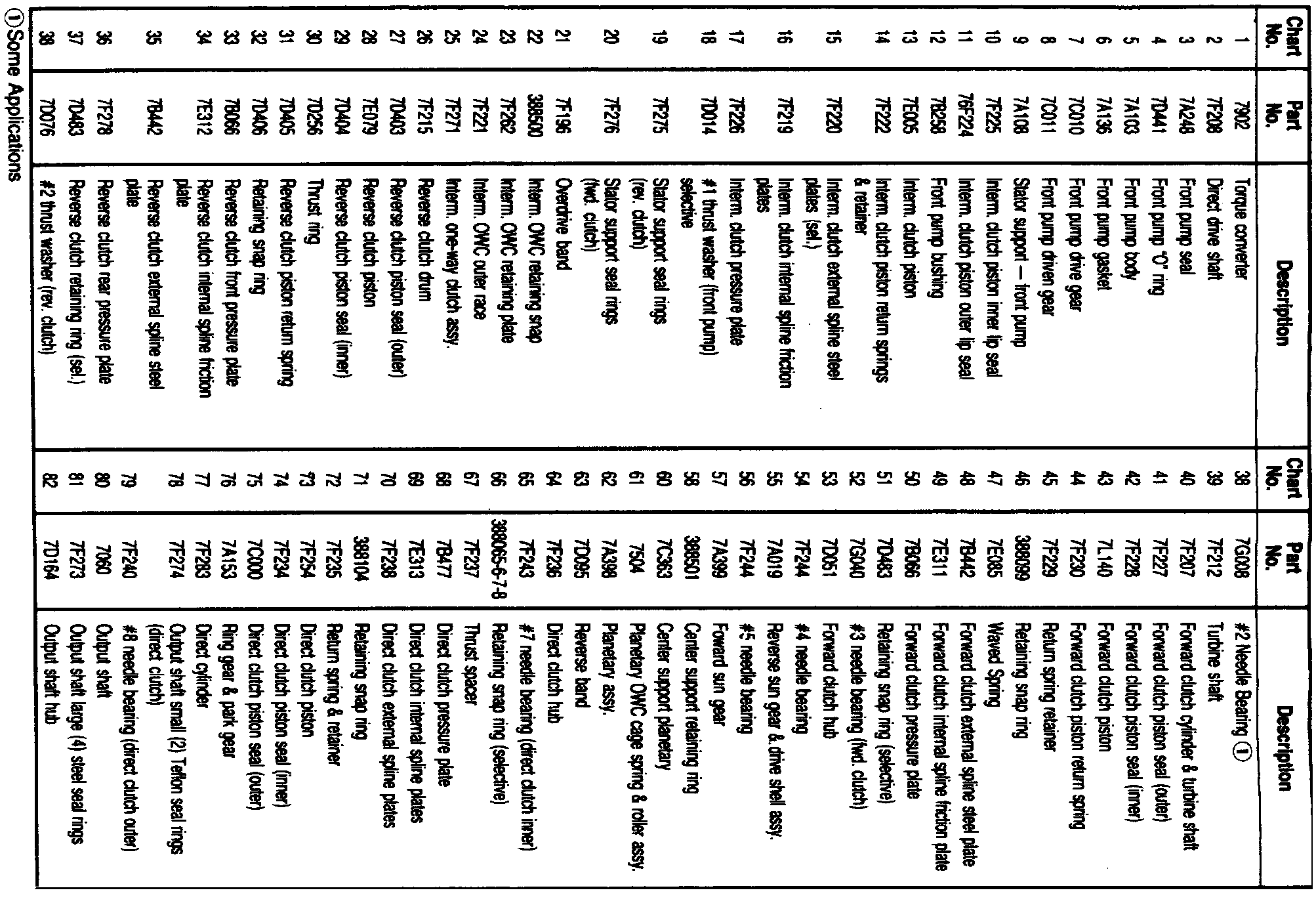
Exploded View Of Ford Automatic Overdrive Transmission (Part 2 Of 3). 2 Wheel Drive Shown, 4 Wheel Drive Similar:
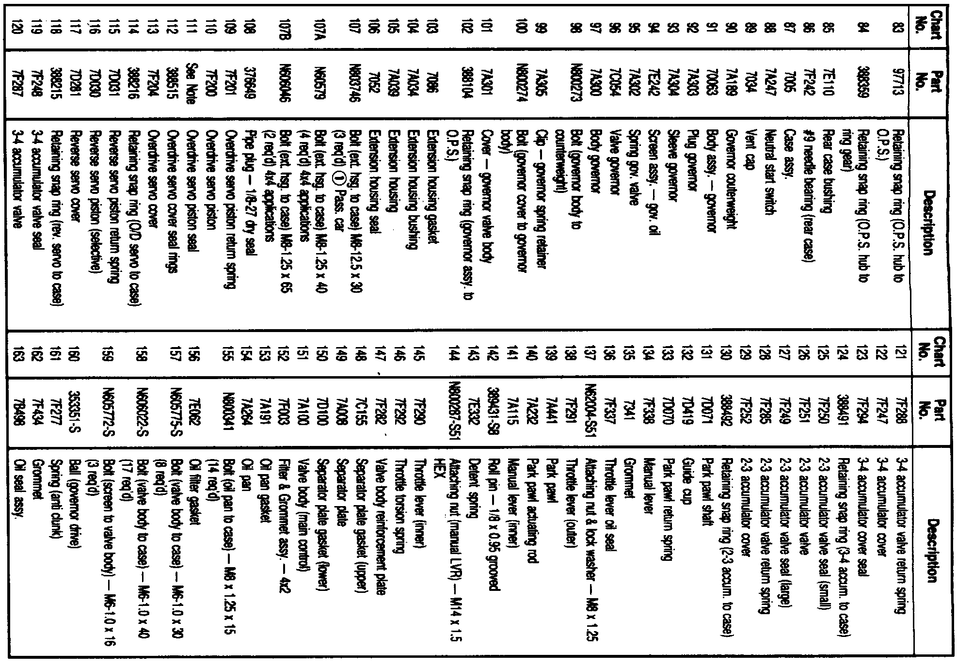
Exploded View Of Ford Automatic Overdrive Transmission (Part 3 Of 3). 2 Wheel Drive Shown, 4 Wheel Drive Similar:
2. Grasp torque converter firmly and pull straight out of transmission.
3. Remove oil pan attaching bolts, oil pan, and gasket, discarding gasket.
4. Remove oil filter attaching bolts, filter, grommet, and gasket discarding gasket.
5. Remove manual lever detent spring and roller assembly.
6. Remove remaining valve body attaching bolts, valve body, and gasket.
NOTE: The four front, one center, and three rear attaching bolts are shorter than the others.
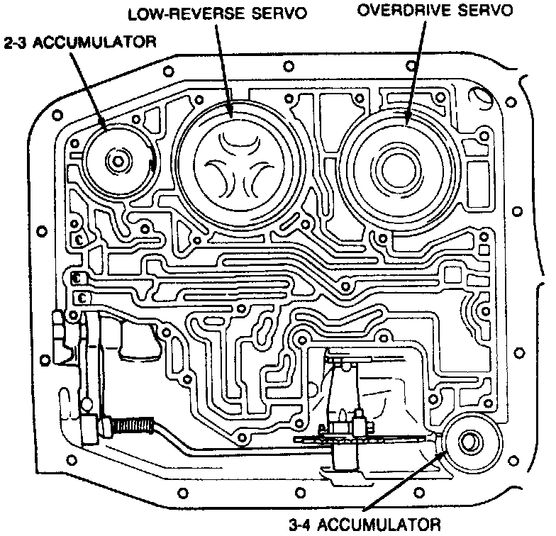
Accumulator And Servo Locations:
7. Using suitable tool, push down on 3-4 accumulator cover and remove retaining ring.
8. Remove 3-4 accumulator cover and the piston return spring, if equipped. Some applications will have an inverted 3-4 accumulator piston design. The inverted piston has a pocket in the piston.
NOTE: Depending on application, one of three accumulator designs will be used: there will be a spring between cover and piston, there will be a spring beneath the piston, or there will no spring. The appearance of the piston and spring will also vary from model to model.
9. If cover sticks in bore, use servo piston remover T80L-77030-B, or equivalent, and air pressure to aid in removal.
NOTE: Ensure portion of tool extends over bore to prevent cover from flying out of bore.
10. Remove 3-4 accumulator piston.
11. Using suitable tool, push down on 2-3 accumulator cover, as shown in the Accumulator And Servo Locations image, and remove retaining ring.
12. Remove 2-3 accumulator cover and piston spring, then the 2-3 accumulator piston.
13. Using suitable tool, press down on low-reverse servo cover, as shown in the Accumulator And Servo Locations image, and remove retaining ring.
14. Remove low-reverse servo piston and piston return spring, using magnet as necessary.
NOTE: The length of the rod attached to the piston may vary in length from transmission to transmission. Three possible lengths may be encountered. A single groove cut into the piston rod indicates the shortest possible length while two and three groove piston rods indicate successively longer rods. To ensure proper assembly, it is important to determine which length piston rod was used in manufacture of transmission.
15. Using suitable tool, push down on overdrive servo cover, as shown in the Accumulator And Servo Locations image, and remove retaining ring.
16. Remove overdrive cover and piston as an assembly. If cover sticks in bore, use servo removal tool T80L-77030-B, or equivalent, to aid in removal.
NOTE: Ensure a portion of tool extends over bore to prevent cover from flying out of bore.
17. Remove overdrive servo spring.
18. Remove direct driveshaft.
19. Remove seven 10 mm pump body attaching bolts.
20. Using slide hammer T59L-100-B and front pump remover adapters T80L-77103-A, or equivalents, remove pump assembly.
21. Remove pump to case gasket.
22. Grasp turbine shaft firmly and pull intermediate clutch pack, intermediate one-way clutch, reverse clutch, and forward clutch out of case as an assembly.
CAUTION: Remove assembly carefully to prevent damage to overdrive band friction material by the reverse clutch drive lugs.
23. Disengage overdrive band from anchor pins and remove from case.
24. Remove forward clutch hub and No.3 needle bearing as an assembly.
25. Remove forward sun gear, No. 5 needle bearing, reverse sun gear and drive shell, and the No.4 needle bearing as an assembly.
26. Remove center support retaining ring, noting position of tabs for proper assembly.
27. Using screwdriver, pry anti-clunk spring out from between center support and case, noting location for proper assembly.
28. Remove center support and planetary carrier as an assembly.
29. Remove reverse ban.
30. If direct clutch hub did not come out with planetary carrier, reach in and lift it out of direct clutch.
31. Remove extension housing attaching bolts and the extension housing, discarding extension housing gasket.
32. Remove retaining ring and governor assembly. To loosen governor from shaft, it may be necessary to tap governor assembly with plastic hammer. If transmission is positioned with output shaft pointing up, do not allow shaft assembly to fall through case when the governor is removed.
33. Remove governor drive ball from output shaft, using magnet if necessary.
34. Remove output shaft ring gear and direct clutch through front of case as an assembly.
35. Remove output shaft No. 9 needle bearing from rear of case.
36. Remove intermediate clutch pack from intermediate one-way clutch.
37. Remove reverse clutch assembly from forward clutch assembly.