Test J
PINPOINT TEST J: THE A/C DOES NOT OPERATE/DOES NOT OPERATE CORRECTLYTest J1-J3:

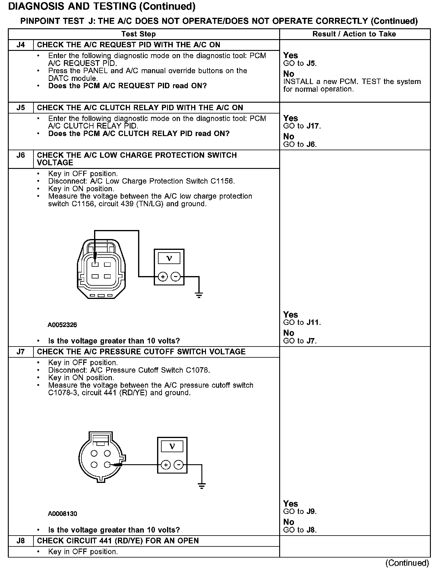
Test J4-J8:
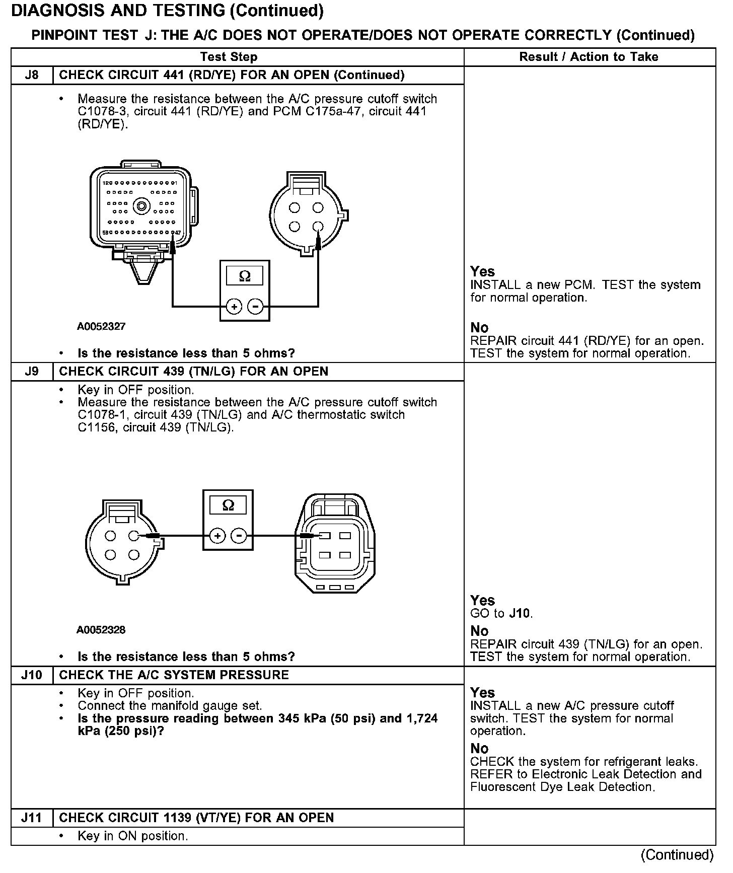
Test J8-J11:
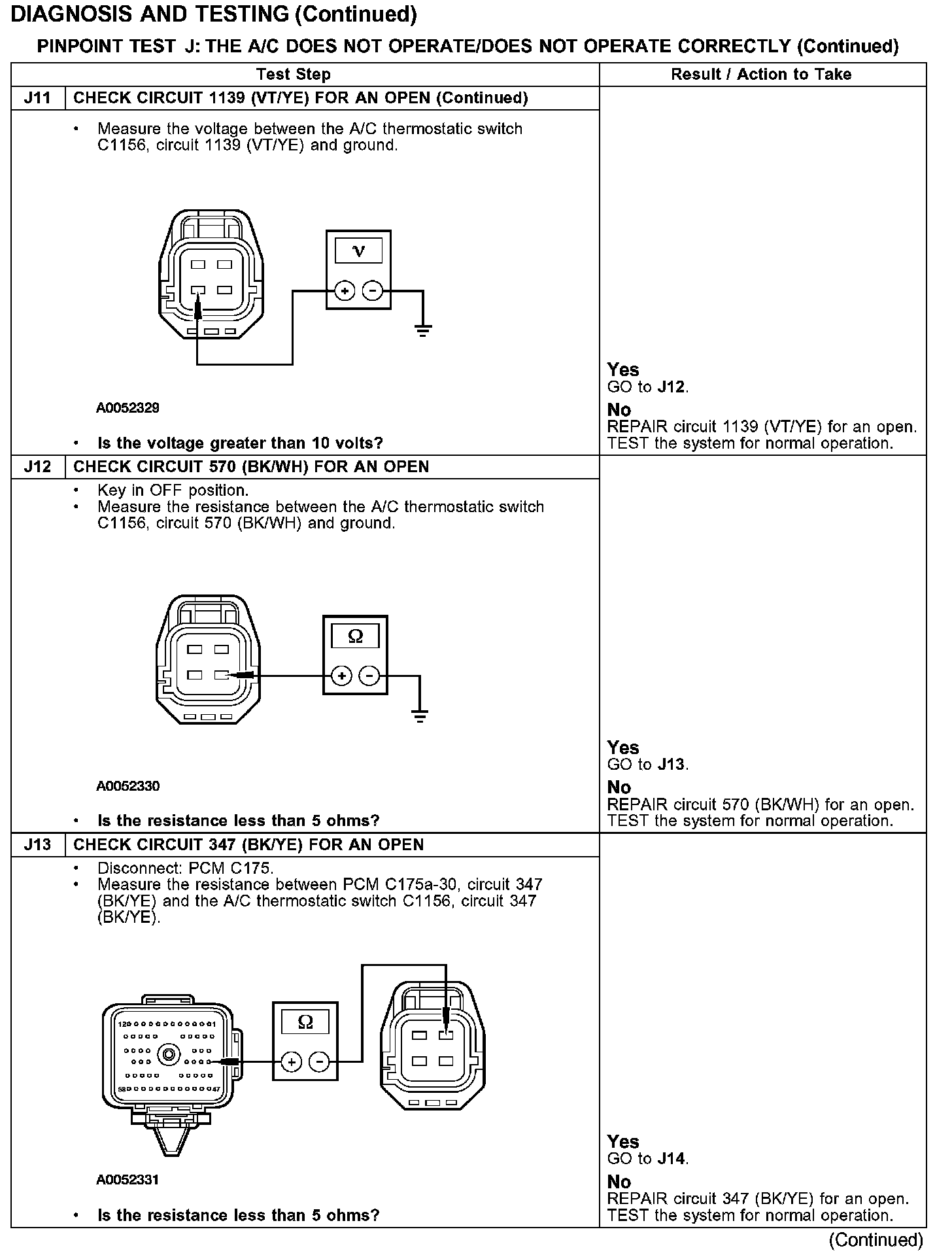
Test J11-J13:
Test J14-J16:

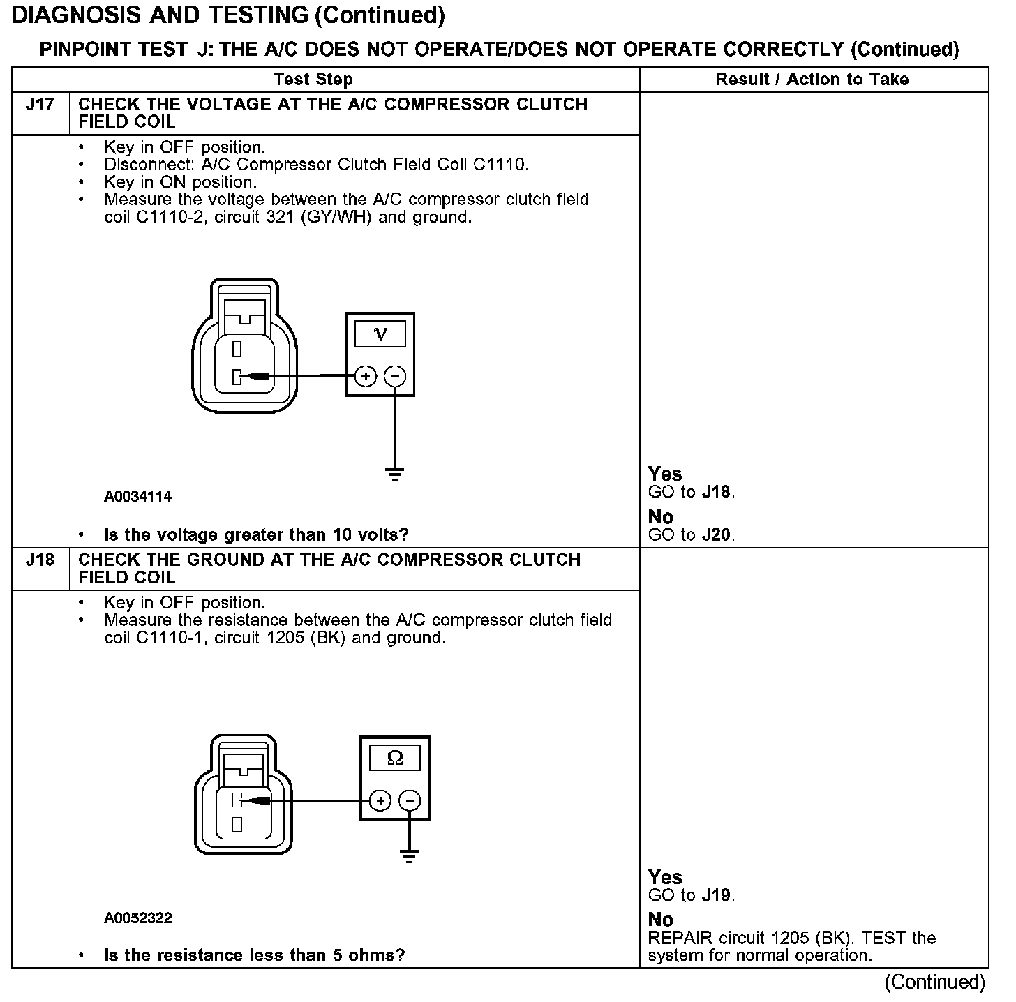
Test J17-J18:
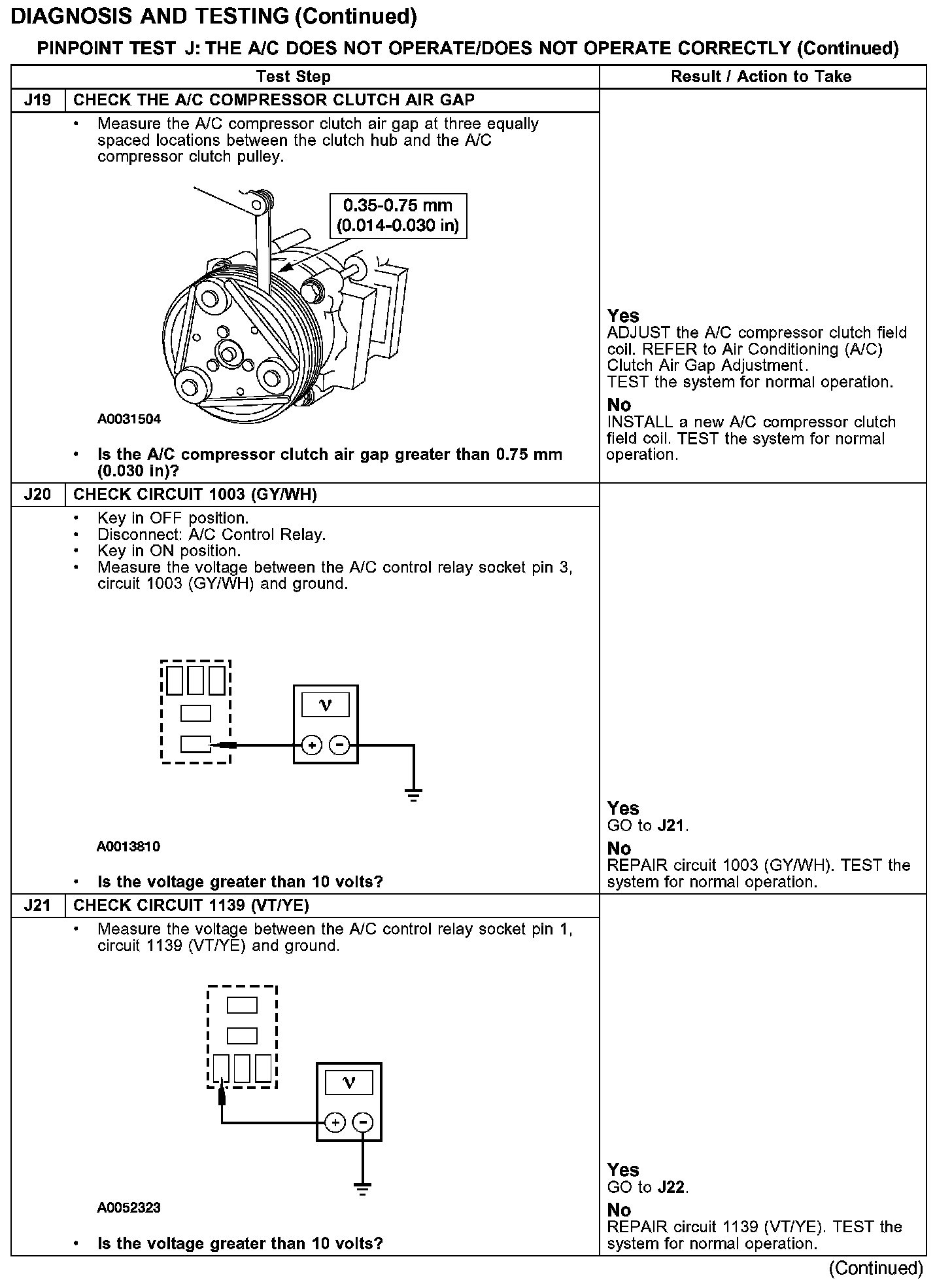
Test J19-J21:
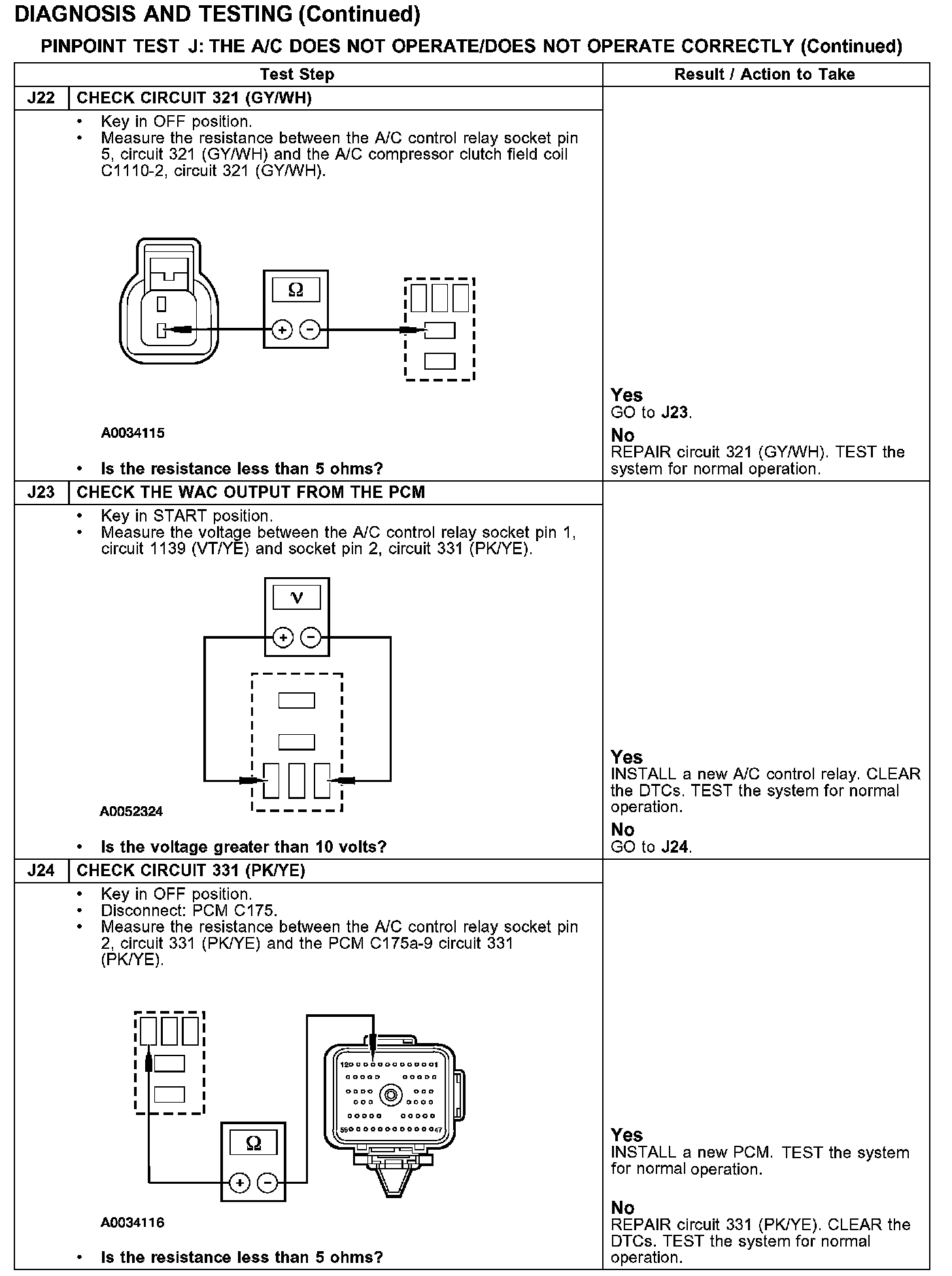
Test J22-J24:
Normal Operation
Under normal operation, the Dual Automatic Temperature Control (DATC) module sends a A/C request signal over the communication bus to the PCM. The thermostatic switch and low charge protection switch receive a ground through circuit 570 (BK/WH). The thermostatic switch receives ignition voltage through circuit 1139 (VT/YE). When the thermostatic switch closes, a signal is sent to the PCM through circuit 347 (BK/YE). When the low charge protection switch closes, ground is provided to the high pressure cutoff switch through circuit 439 (TN/LG). When the high pressure cutoff switch closes, a ground signal is received by the PCM through circuit 441 (RD/YE).
The PCM provides a ground for the A/C clutch relay coil through circuit 331 (PK/YE). The A/C clutch relay coil receives ignition voltage through circuit 1139 (VT/YE). Ignition voltage for the A/C clutch relay switch is provided through circuit 1003 (GY/WH). When the relay is activated, ignition voltage is supplied to the A/C clutch solenoid through circuit 321 (GY/WH). Ground is supplied for the A/C clutch through circuit 1205 (BK).
Possible Causes
- An open in circuits 441 (RD/YE), 439 (TN/LG), 1139 (VT/YE), 570 (BK/WH), 347 (BK/YE), 1205 (BK), 1003 (GY/WH), 1139 (VT/YE), 321 (GY/WH) or 331 (PK/YE).
- PCM.
- DATC module.
- A/C low charge protection switch.
- A/C thermostatic switch.
- A/C compressor clutch field coil.
- A/C pressure cutoff switch.
- A/C control relay.