Rear View Mirrors - Interior
Rear View Mirrors - Interior
Pinpoint Tests
Pinpoint Test F: The Auto-Dimming Mirror Does Not Operate Correctly
Refer to Wiring Diagram Set 124, Power Mirrors for schematic and connector information. [1][2]Diagrams By Number
Normal Operation
Under normal operation the interior auto-dimming mirror receives voltage from the Smart Junction Box (SJB). The interior auto-dimming mirror contains 2 photoelectric sensors: one in the front of the interior rear view mirror and one mounted on the glass side of the mirror. If the sensors are blocked, the LH exterior mirror and auto-dimming feature may not operate correctly. Always verify both sensors are not physically blocked before attempting to diagnose auto-dimming mirror concerns. Whenever the gear selector lever is placed in REVERSE, the interior auto-dimming mirror temporarily disables the auto-dimming feature. The auto-dimming feature is enabled again when the gear selector lever is moved out of REVERSE.
This pinpoint test is intended to diagnose the following:
- Fuse
- Wiring, terminals or connectors
- Interior auto-dimming mirror
- LH exterior mirror auto-dimming glass
- LH exterior auto-dimming mirror (if equipped)
PINPOINT TEST F : THE AUTO-DIMMING MIRROR DOES NOT OPERATE CORRECTLY
NOTICE: Use the correct probe adapter(s) from the Flex Probe Kit when making measurements. Failure to use the correct probe adapter(s) may damage the connector.
NOTE: If the Transmission Range (TR) sensor is malfunctioning and the backup lamps are on all the time or do not turn on, the auto-dimming interior mirror will not darken or return to normal view.
F1 CHECK THE OPERATION OF THE BACKUP LAMPS
- Ignition ON.
- Move the selector lever through the entire range.
Do the backup lamps illuminate and only in REVERSE?
Yes
MKZ only: If the LH exterior mirror only is always dim, REPAIR circuit LRD12 (BU/GY) for a short to voltage. TEST the system for normal operation.
MKZ only: If the LH exterior mirror only does not dim correctly, GO to F10.
MKZ only: If the interior mirror only does not dim correctly and the LH exterior mirror does dim correctly, INSTALL a new interior mirror, REFER to Interior Rear View Mirror . TEST the system for normal operation.
MKZ only: If the LH exterior mirror and interior mirror does not dim correctly, GO to F2.
Fusion only: If the interior mirror does not operate correctly, GO to F2.
No
REFER to Lighting and Horns to diagnose the backup lamps.
F2 VERIFY THAT THE FORWARD AND REARWARD FACING SENSORS ARE NOT BLOCKED
- Visually verify that the forward and rearward facing sensors are not blocked. Sources of blockage can include:
- stickers, window decals or tags.
- fold-down screens for TVs or DVD players.
- non-OEM window tinting.
Were either of the sensors blocked?
Yes
If possible, REMOVE the blockage. TEST the system for normal operation. If the blockage cannot be removed, ADVISE the customer of the correct operation of the interior auto-dimming mirror.
No
GO to F3.
F3 CHECK THE OPERATION OF THE INTERIOR AUTO-DIMMING MIRROR - DAYLIGHT CONDITIONS
- Ignition ON.
- Without video display: Use a bright lamp to simultaneously illuminate the forward-facing sensor and the rearward-facing sensor. The mirror should adjust to a high reflectance mode (mirror will be clear).

- With video display: Use a bright lamp to simultaneously illuminate the forward-facing sensor and the rearward-facing sensor. The mirror should adjust to a high reflectance mode (mirror will be clear).

Does the mirror adjust to the high reflectance (clear) mode?
Yes
GO to F4.
No
INSTALL a new interior mirror. REFER to Interior Rear View Mirror . TEST the system for normal operation.
F4 CHECK THE OPERATION OF THE INTERIOR AUTO-DIMMING MIRROR - NIGHTTIME CONDITIONS WITH GLARE
- Ignition ON.
- Without video display: Simulate nighttime conditions with glare:
- NOTE: Covering the sensor with a finger or hand is not adequate.
Cover the forward-facing sensor with black electrical tape or other dark material.
- Illuminate the rearward-facing sensor. The mirror should darken to a lower reflectance mode.

- With video display: Simulate nighttime conditions with glare:
- NOTE: Covering the sensor with a finger or hand is not adequate.
Cover the forward-facing sensor with black electrical tape or other dark material.
- Illuminate the rearward-facing sensor. The mirror should darken to a lower reflectance mode.

Did the mirror darken to a lower reflectance (darker) mode?
Yes
GO to F5.
No
GO to F7.
F5 CHECK THE OPERATION OF THE INTERIOR AUTO-DIMMING MIRROR - NIGHTTIME CONDITIONS WITHOUT GLARE
- Ignition ON.
- Without video display: Simulate nighttime conditions without glare:
- NOTE: Covering the sensor with a finger or hand is not adequate.
Cover the rearward-facing sensor. The mirror should adjust to the high reflectance mode.

- With video display: Simulate nighttime conditions without glare:
- NOTE: Covering the sensor with a finger or hand is not adequate.
Cover the rearward-facing sensor. The mirror should adjust to the high reflectance mode.

Did the mirror adjust to the high reflectance (clear) mode?
Yes
GO to F6.
No
GO to F7.
F6 CHECK THE OPERATION OF THE INTERIOR AUTO-DIMMING MIRROR - NIGHTTIME CONDITIONS WITH THE VEHICLE IN REVERSE
- Ignition ON.
- Without video display: Simulate nighttime conditions with glare:
- NOTE: Covering the sensor with a finger or hand is not adequate.
Cover the forward-facing sensor with black electrical tape or other dark material.
- Illuminate the rearward-facing sensor.
- With video display: Simulate nighttime conditions with glare:
- NOTE: Covering the sensor with a finger or hand is not adequate.
Cover the forward-facing sensor with black electrical tape or other dark material.
- Illuminate the rearward-facing sensor.
- Select REVERSE.
Did the mirror adjust to a high reflectance (clear) mode?
Yes
The system is operating normally at this time. REVIEW operation of the interior auto-dimming mirror feature with the customer.
No
GO to F7.
F7 CHECK THE VOLTAGE TO THE INTERIOR MIRROR
- Ignition OFF.
- Disconnect: Interior Mirror C911 or C9039 (with video display).
- Ignition ON.
- Measure the voltage between ground and:
- Without video display, interior auto-dimming mirror C911-1, circuit CBP41 (BU), harness side.
- With video display, interior auto-dimming mirror C9039-1, circuit CBP41 (BU), harness side.

Is the voltage greater than 10 volts?
Yes
GO to F8.
No
VERIFY SJB (Smart Junction Box) fuse 41 (15A) is OK. If OK, REPAIR the circuit. If not OK, REFER to the Wiring Diagrams to identify the possible causes of the circuit short. TEST the system for normal operation. [1][2]Diagrams By Number
F8 CHECK THE GROUND TO THE INTERIOR MIRROR
- Ignition OFF.
- Without video display: Measure the resistance between interior auto-dimming mirror C911-4, circuit GD139 (BK/YE), harness side and ground.

- With video display: Measure the resistance between interior auto-dimming mirror C9039-3, circuit GD139 (BK/YE), harness side and ground.

Is the resistance less than 5 ohms?
Yes
GO to F9.
No
REPAIR the circuit. TEST the system for normal operation.
F9 CHECK REVERSE INPUT CIRCUIT
- Ignition ON.
- Select REVERSE.
- Without video display: Measure the voltage between interior auto-dimming mirror C911-3, circuit CLS10 (GN/BN), harness side and ground.

- With video display: Measure the voltage between interior auto-dimming mirror C9039-2, circuit CLS10 (GN/BN), harness side and ground.

Is the voltage greater than 10 volts?
Yes
INSTALL a new interior auto-dimming mirror. REFER to Interior Rear View Mirror . TEST the system for normal operation.
No
REPAIR the circuit. TEST the system for normal operation.
F10 CHECK CIRCUIT LRD12 (BU/GY) FOR VOLTAGE
- Ignition OFF.
- Disconnect: LH Exterior Mirror C522.
- Ignition ON.
- Simulate nighttime conditions with glare:
- NOTE: Covering the sensor with a finger or hand is not adequate.
Cover the forward-facing sensor with black electrical tape or other dark material.
- Illuminate the rearward-facing sensor. The mirror should darken to a lower reflectance mode.
- Measure the voltage between LH exterior mirror C522-9, circuit LRD12 (BU/GY), harness side and ground.

Is the voltage greater than 1 volt?
Yes
GO to F11.
No
GO to F13.
F11 CHECK CIRCUIT RRD12 (BN) FOR GROUND
- Measure the resistance between LH exterior mirror C522-8, circuit RRD12 (BN), harness side and ground.

Is the resistance greater than 10,000 ohms?
Yes
GO to F12.
No
CHECK the LH exterior mirror jumper harness between the vehicle harness and the exterior mirror glass for shorted or open circuits and damaged or pushed-out pins. If the jumper harness is not OK, REPAIR the jumper harness. If the jumper harness cannot be repaired, INSTALL a new LH exterior mirror. REFER to Exterior Mirror . If the jumper harness is OK, INSTALL a new LH exterior mirror glass. REFER to Exterior Mirror Glass . TEST the system for normal operation.
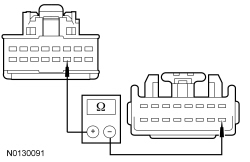
F12 CHECK CIRCUIT RRD12 (BN) FOR AN OPEN
- Ignition OFF.
- Disconnect: Interior Mirror C911.
- Measure the resistance between LH exterior mirror C522-8, circuit RRD12 (BN), harness side and interior auto-dimming mirror C911-15, circuit RRD12 (BN), harness side.

Is the resistance less than 5 ohms?
Yes
INSTALL new interior mirror. REFER to Interior Rear View Mirror . TEST the system for normal operation.
No
REPAIR the circuit. TEST the system for normal operation.
F13 CHECK CIRCUIT LRD12 (BU/GY) FOR AN OPEN
- Ignition OFF.
- Disconnect: Interior Mirror C911.
- Measure the resistance between LH exterior mirror C522-9, circuit LRD12 (BU/GY), harness side and interior auto-dimming mirror C911-11, circuit LRD12 (BU/GY), harness side.
Is the resistance less than 5 ohms?
Yes
GO to F14.
No
REPAIR the circuit. TEST the system for normal operation.
F14 CHECK CIRCUIT LRD12 (BU/GY) FOR A SHORT TO GROUND
- Measure the resistance between ground and interior auto-dimming mirror C911-11, circuit LRD12 (BU/GY), harness side.

Is the resistance greater than 10,000 ohms?
Yes
INSTALL new interior mirror. REFER to Interior Rear View Mirror . TEST the system for normal operation.
No
REPAIR the circuit. TEST the system for normal operation.