Pinpoint Test H: The Power Seat Does Not Move Horizontally/Vertically/Recline - Driver
Seats
Pinpoint Test H: The Power Seat Does Not Move Horizontally/Vertically/Recline - Driver
Refer to Wiring Diagram Set 120, Power Seats for schematic and connector information. [1][2]Diagrams By Number
Normal Operation
The driver seat control switch is supplied voltage and ground. When the driver seat control switch is activated, voltage and ground is supplied to the applicable seat track motor to move the seat to the desired position. There are 3 seat track motors that combine to move the seat cushion horizontally (forward/rearward) and vertically (front up/down and rear up/down). If a new motor on the seat track needs to be installed, it is necessary to install an entire seat track assembly. There is an additional motor in the seat recliner mechanism to move the seat backrest forward and rearward.
This pinpoint test is intended to diagnose the following:
- Wiring, terminals or connectors
- Seat control switch
- Seat track
- Seat recliner motor
PINPOINT TEST H : THE POWER SEAT DOES NOT MOVE HORIZONTALLY/VERTICALLY/RECLINE - DRIVER
NOTE: If a seat equipped with a seat mounted side air bag is being serviced, the Supplemental Restraint System (SRS) must be depowered. Refer to Restraints and Safety Systems &/or Air Bag Systems.
NOTE: The air bag warning lamp illuminates when the Restraints Control Module (RCM) fuse is removed and the ignition switch is ON. This is normal operation and does not indicate an SRS (Supplemental Restraint System) fault.
NOTE: The SRS (Supplemental Restraint System) must be fully operational and free of faults before releasing the vehicle to the customer.
H1 CHECK THE HORIZONTAL MOTOR FOR CORRECT OPERATION
- Operate the driver power seat forward and rearward.
Does the seat move horizontally?
Yes
GO to H2.
No
GO to H3.
H2 CHECK THE RECLINER MOTOR FOR CORRECT OPERATION
- Recline the driver backrest forward and rearward.
Does the seat backrest recline forward and rearward?
Yes
GO to H6.
No
GO to H13.
H3 CHECK VOLTAGE TO THE DRIVER SEAT HORIZONTAL MOTOR
- Ignition OFF.
- Depower the SRS (Supplemental Restraint System). Refer to Supplemental Restraint System (SRS) Depowering and Repowering in the General Procedures portion of Restraints and Safety Systems &/or Air Bag Systems.
- Disconnect: Driver Seat Side Air Bag C327.
- Disconnect: Driver Seat Motor C357.
- WARNING: Make sure no one is in the vehicle and there is nothing blocking or placed in front of any air bag module when the battery is connected. Failure to follow these instructions may result in serious personal injury in the event of an accidental deployment.
Connect the battery ground cable.
- NOTE: During the following step, the voltage being measured changes polarity dependent upon which direction the seat control switch is activated.
Measure the voltage between driver seat motor C357-6, circuit CPS23 (GN/VT), harness side and C357-3, circuit CPS22 (BN), harness side, while operating the seat control switch horizontal adjust forward and rearward.

Is the voltage greater than 10 volts when the seat control switch is operated and 0 volt in the rest position?
Yes
INSTALL a new driver seat track assembly. REFER to Seat Track . TEST the system for normal operation.
DISCONNECT the battery ground cable. CONNECT driver seat side air bag module C327. REPOWER the SRS (Supplemental Restraint System). REFER to Restraints and Safety Systems &/or Air Bag Systems.
No
GO to H4.
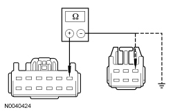
H4 CHECK HORIZONTAL MOTOR CIRCUIT FOR AN OPEN AND SHORT TO GROUND
- Disconnect: Driver Seat Control Switch C360.
- Measure the resistance between:
- driver seat control switch C360-9, circuit CPS23 (GN/VT), harness side and driver seat motor C357-6, circuit CPS23 (GN/VT), harness side.
- driver seat control switch C360-9, circuit CPS23 (GN/VT), harness side and ground.

Is the resistance less than 5 ohms between the driver seat motor and the driver seat control switch; and greater than 10,000 ohms between the driver seat control switch and ground?
Yes
GO to H5.
No
REPAIR the circuit. TEST the system for normal operation.
DISCONNECT the battery ground cable. CONNECT driver seat side air bag module C327. REPOWER the SRS (Supplemental Restraint System). REFER to Restraints and Safety Systems &/or Air Bag Systems.
H5 CHECK HORIZONTAL MOTOR CIRCUIT FOR AN OPEN AND SHORT TO GROUND
- Measure the resistance between:
- driver seat control switch C360-4, circuit CPS22 (BN), harness side and driver seat motor C357-3, circuit CPS23 (GN/VT), harness side.
- driver seat control switch C360-4, circuit CPS22 (BN), harness side and ground.

Is the resistance less than 5 ohms between the driver seat motor and the driver seat control switch; and greater than 10,000 ohms between the driver seat control switch and ground?
Yes
INSTALL a new driver seat control switch. REFER to Seat Control Switch . TEST the system for normal operation.
DISCONNECT the battery ground cable. CONNECT driver seat side air bag module C327. REPOWER the SRS (Supplemental Restraint System). REFER to Restraints and Safety Systems &/or Air Bag Systems.
No
REPAIR the circuit. TEST the system for normal operation.
DISCONNECT the battery ground cable. CONNECT driver seat side air bag module C327. REPOWER the SRS (Supplemental Restraint System). REFER to Restraints and Safety Systems &/or Air Bag Systems.
H6 DETERMINE THE SEAT HEIGHT ADJUST FAILURE
- Operate the front and rear seat height adjustments.
Does the seat front and rear height adjust up and down?
Yes
If only front height adjust operates, GO to H7.
If only rear height adjust operates, GO to H10.
No
INSTALL a new driver seat control switch. REFER to Seat Control Switch . TEST the system for normal operation.
DISCONNECT the battery ground cable. CONNECT driver seat side air bag module C327. REPOWER the SRS (Supplemental Restraint System). REFER to Restraints and Safety Systems &/or Air Bag Systems.
H7 CHECK VOLTAGE TO THE DRIVER SEAT REAR HEIGHT MOTOR
- Ignition OFF.
- Depower the SRS (Supplemental Restraint System). Refer to Supplemental Restraint System (SRS) Depowering and Repowering in the General Procedures portion of Restraints and Safety Systems &/or Air Bag Systems.
- Disconnect: Driver Seat Side Air Bag C327.
- Disconnect: Driver Seat Motor C357.
- WARNING: Make sure no one is in the vehicle and there is nothing blocking or placed in front of any air bag module when the battery is connected. Failure to follow these instructions may result in serious personal injury in the event of an accidental deployment.
Connect the battery ground cable.
- NOTE: During the following step, the voltage being measured changes polarity dependent upon which direction the seat control switch is activated.
Measure the voltage between driver seat motor C357-1, circuit CPS27 (BU/BN), harness side and C357-4, circuit CPS26 (YE/BU), harness side, while operating the seat control switch rear height adjust up and down.

Is the voltage greater than 10 volts when the seat control switch is operated and 0 volt in the rest position?
Yes
INSTALL a new driver seat track assembly. REFER to Seat Track . TEST the system for normal operation.
DISCONNECT the battery ground cable. CONNECT driver seat side air bag module C327. REPOWER the SRS (Supplemental Restraint System). REFER to Restraints and Safety Systems &/or Air Bag Systems.
No
GO to H8.
H8 CHECK REAR HEIGHT MOTOR CIRCUIT FOR AN OPEN AND SHORT TO GROUND
- Disconnect: Driver Seat Control Switch C360.
- Measure the resistance between:
- driver seat control switch C360-1, circuit CPS27 (BU/BN), harness side and driver seat motor C357-1, circuit CPS27 (BU/BN), harness side.
- driver seat control switch C360-1, circuit CPS27 (BU/BN), harness side and ground.
Is the resistance less than 5 ohms between the driver seat motor and the driver seat control switch; and greater than 10,000 ohms between the driver seat control switch and ground?
Yes
GO to H9.
No
REPAIR the circuit. TEST the system for normal operation.
DISCONNECT the battery ground cable. CONNECT driver seat side air bag module C327. REPOWER the SRS (Supplemental Restraint System). REFER to Restraints and Safety Systems &/or Air Bag Systems.
H9 CHECK REAR HEIGHT MOTOR CIRCUIT FOR AN OPEN AND SHORT TO GROUND
- Measure the resistance between:
- driver seat control switch C360-12, circuit CPS26 (YE/BU), harness side and driver seat motor C357-4, circuit CPS26 (YE/BU), harness side.
- driver seat control switch C360-12, circuit CPS26 (YE/BU), harness side and ground.

Is the resistance less than 5 ohms between the driver seat motor and the driver seat control switch; and greater than 10,000 ohms between the driver seat control switch and ground?
Yes
INSTALL a new driver seat control switch. REFER to Seat Control Switch . TEST the system for normal operation.
DISCONNECT the battery ground cable. CONNECT driver seat side air bag module C327. REPOWER the SRS (Supplemental Restraint System). REFER to Restraints and Safety Systems &/or Air Bag Systems.
No
REPAIR the circuit. TEST the system for normal operation.
DISCONNECT the battery ground cable. CONNECT driver seat side air bag module C327. REPOWER the SRS (Supplemental Restraint System). REFER to Restraints and Safety Systems &/or Air Bag Systems.
H10 CHECK VOLTAGE TO THE DRIVER SEAT FRONT HEIGHT MOTOR
- Ignition OFF.
- Depower the SRS (Supplemental Restraint System). Refer to Supplemental Restraint System (SRS) Depowering and Repowering in the General Procedures portion of Restraints and Safety Systems &/or Air Bag Systems.
- Disconnect: Driver Seat Side Air Bag C327.
- Disconnect: Driver Seat Motor C357.
- WARNING: Make sure no one is in the vehicle and there is nothing blocking or placed in front of any air bag module when the battery is connected. Failure to follow these instructions may result in serious personal injury in the event of an accidental deployment.
Connect the battery ground cable.
- NOTE: During the following step, the voltage being measured changes polarity dependent upon which direction the seat control switch is activated.
Measure the voltage between driver seat motor C357-2, circuit CPS25 (WH/VT), harness side and C357-5, circuit CPS24 (GY), harness side, while operating the seat control switch front height adjust up and down.

Is the voltage greater than 10 volts when the seat control switch is operated and 0 volt in the rest position?
Yes
INSTALL a new driver seat track assembly. REFER to Seat Track . TEST the system for normal operation.
DISCONNECT the battery ground cable. CONNECT driver seat side air bag module C327. REPOWER the SRS (Supplemental Restraint System). REFER to Restraints and Safety Systems &/or Air Bag Systems.
No
GO to H11.
H11 CHECK FRONT HEIGHT MOTOR CIRCUIT FOR AN OPEN AND SHORT TO GROUND
- Disconnect: Driver Seat Control Switch C360.
- Measure the resistance between:
- driver seat control switch C360-2, circuit CPS25 (WH/VT), harness side and driver seat motor C357-2, circuit CPS25 (WH/VT), harness side.
- driver seat control switch C360-2, circuit CPS25 (WH/VT), harness side and ground.

Is the resistance less than 5 ohms between the driver seat motor and the driver seat control switch; and greater than 10,000 ohms between the driver seat control switch and ground?
Yes
GO to H12.
No
REPAIR the circuit. TEST the system for normal operation.
DISCONNECT the battery ground cable. CONNECT driver seat side air bag module C327. REPOWER the SRS (Supplemental Restraint System). REFER to Restraints and Safety Systems &/or Air Bag Systems.
H12 CHECK FRONT HEIGHT MOTOR CIRCUIT FOR AN OPEN AND A SHORT TO GROUND
- Measure the resistance between:
- driver seat control switch C360-6, circuit CPS24 (GY) harness side, and driver seat motor C357-5, circuit CPS24 (GY), harness side.
- driver seat control switch C360-6, circuit CPS24 (GY), harness side and ground.

Is the resistance less than 5 ohms between the driver seat motor and the driver seat control switch; and greater than 10,000 ohms between the driver seat control switch and ground?
Yes
INSTALL a new driver seat control switch. REFER to Seat Control Switch . TEST the system for normal operation.
DISCONNECT the battery ground cable. CONNECT driver seat side air bag module C327. REPOWER the SRS (Supplemental Restraint System). REFER to Restraints and Safety Systems &/or Air Bag Systems.
No
REPAIR the circuit. TEST the system for normal operation.
DISCONNECT the battery ground cable. CONNECT driver seat side air bag module C327. REPOWER the SRS (Supplemental Restraint System). REFER to Restraints and Safety Systems &/or Air Bag Systems.
H13 CHECK VOLTAGE TO THE DRIVER SEAT RECLINER MOTOR
- Ignition OFF.
- Depower the SRS (Supplemental Restraint System). Refer to Supplemental Restraint System (SRS) Depowering and Repowering in the General Procedures portion of Restraints and Safety Systems &/or Air Bag Systems.
- Disconnect: Driver Seat Side Air Bag C327.
- Disconnect: Driver Seat Recliner Motor C3187.
- WARNING: Make sure no one is in the vehicle and there is nothing blocking or placed in front of any air bag module when the battery is connected. Failure to follow these instructions may result in serious personal injury in the event of an accidental deployment.
Connect the battery ground cable.
- NOTE: During the following step, the voltage being measured changes polarity dependent upon which direction the seat control switch is activated.
Measure the voltage between driver seat recliner motor C3187-1, circuit CPS29 (WH/BN), harness side and C3187-5, circuit CPS30 (VT/BN), harness side, while operating the seat control switch recline adjust forward and rearward.

Is the voltage greater than 10 volts when the seat control switch is operated and 0 volt in the rest position?
Yes
INSTALL a new driver seat recliner motor. REFER to Seat Recliner Motor . TEST the system for normal operation.
DISCONNECT the battery ground cable. CONNECT driver seat side air bag module C327. REPOWER the SRS (Supplemental Restraint System). REFER to Restraints and Safety Systems &/or Air Bag Systems.
No
GO to H14.
H14 CHECK RECLINER MOTOR CIRCUIT FOR AN OPEN AND SHORT TO GROUND
- Disconnect: Driver Seat Control Switch C360.
- Measure the resistance between:
- driver seat control switch C360-11, circuit CPS29 (WH/BN), harness side and driver seat recliner motor C3187-1, circuit CPS29 (WH/BN), harness side.
- driver seat control switch C360-11, circuit CPS29 (WH/BN), harness side and ground.

Is the resistance less than 5 ohms between the driver seat recliner motor and the driver seat control switch; and greater than 10,000 ohms between the driver seat control switch and ground?
Yes
GO to H15.
No
REPAIR the circuit. TEST the system for normal operation.
DISCONNECT the battery ground cable. CONNECT driver seat side air bag module C327. REPOWER the SRS (Supplemental Restraint System). REFER to Restraints and Safety Systems &/or Air Bag Systems.
H15 CHECK RECLINER MOTOR CIRCUIT FOR AN OPEN AND SHORT TO GROUND
- Measure the resistance between:
- driver seat control switch C360-8, circuit CPS30 (VT/BN) harness side, and driver seat recliner motor C3187-5, circuit CPS30 (VT/BN), harness side.
- driver seat control switch C360-8, circuit CPS30 (VT/BN), harness side and ground.

Is the resistance less than 5 ohms between the driver seat recliner motor and the driver seat control switch; and greater than 10,000 ohms between the seat control switch and ground?
Yes
INSTALL a new driver seat control switch. REFER to Seat Control Switch . TEST the system for normal operation.
DISCONNECT the battery ground cable. CONNECT driver seat side air bag module C327. REPOWER the SRS (Supplemental Restraint System). REFER to Restraints and Safety Systems &/or Air Bag Systems.
No
REPAIR the circuit. TEST the system for normal operation.
DISCONNECT the battery ground cable. CONNECT driver seat side air bag module C327. REPOWER the SRS (Supplemental Restraint System). REFER to Restraints and Safety Systems &/or Air Bag Systems.