Pinpoint Test A: The Wipers are Inoperative
Wipers and Washers
Pinpoint Test A: The Wipers are Inoperative
Refer to Wiring Diagram Set 81, Wipers and Washers for schematic and connector information. [1][2]Diagrams By Number
Normal Operation
The wiper/washer module is hot at all times through circuit SBB09 (RD). When the ignition switch is in the RUN or ACCESSORY position, voltage is supplied to the wiper/washer module through circuit CBP45 (YE). The wiper/washer module and wiper motor are grounded through circuit GD121 (BK/YE). The multifunction switch is grounded through circuit GD116 (BK/VT). The multifunction switch sends open and ground input signals to the wiper/washer module through circuits CRW17 (GN/VT), CRW18 (VT/WH), CRW19 (BU/OG) and CRW08 (VT/OG) in order to activate the wiper motor to the requested modes. The wiper/washer module supplies voltage to the wiper motor through circuits CRW16 [(GY/BN) low] and CRW15 [(BN/WH) high].
This pinpoint test is intended to diagnose the following:
- Fuse(s)
- Wiring, terminals or connectors
- Multifunction switch
- Wiper motor
- Wiper/washer module
PINPOINT TEST A : THE WIPERS ARE INOPERATIVE
NOTICE: Use the correct probe adapter(s) from the Flex Probe Kit when making measurements. Failure to use the correct probe adapter(s) may damage the connector.
A1 CHECK WIPER MOTOR GROUND
- Ignition OFF.
- Disconnect: Wiper Motor C125.
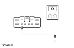
- Measure the resistance between front wiper motor C125-4, circuit GD121 (BK/YE), harness side and ground.

Is the resistance less than 5 ohms?
Yes
GO to A2.
No
REPAIR the circuit. TEST the system for normal operation.
A2 CHECK WIPER MOTOR FOR VOLTAGE
- Ignition ON.
- With the multifunction switch in the low position, measure the voltage between wiper motor C125-5, circuit CRW16 (GY/BN), harness side and ground.

Is the voltage greater than 10 volts?
Yes
INSTALL a new wiper motor. REFER to Wiper Motor . TEST the system for normal operation.
No
GO to A3.
A3 CHECK WIPER MOTOR HIGH/LOW CIRCUITS FOR AN OPEN
- Ignition OFF.
- Disconnect: Wiper/Washer Module C2157.
- Measure the resistance between wiper/washer module C2157-4, circuit CRW16 (GY/BN), harness side and wiper motor C125-5, circuit CRW16 (GY/BN), harness side; and between wiper/washer module C2157-11, circuit CRW15 (BN/WH), harness side and wiper motor C125-3, circuit CRW15 (BN/WH), harness side.

Are the resistances less than 5 ohms?
Yes
GO to A4.
No
REPAIR the circuit(s). TEST the system for normal operation
A4 CHECK WIPER/WASHER MODULE FOR VOLTAGE
- Ignition ON.
- Measure the voltage between wiper/washer module C2157-9, circuit SBB09 (RD), harness side and ground; and between wiper/washer module C2157-10, circuit CBP45 (YE), harness side and ground.

Is the voltage greater than 10 volts?
Yes
GO to A5.
No
VERIFY Battery Junction Box (BJB) fuse 9 (20A) and Smart Junction Box (SJB) fuse 45 (5A) are OK. If OK, REPAIR the circuit. TEST the system for normal operation.
If not OK, REFER to the Wiring Diagrams to identify possible causes of the circuit short. REPAIR the circuit. TEST the system for normal operation. [1][2]Diagrams By Number
A5 CHECK WIPER/WASHER MODULE FOR GROUND
- Ignition OFF.
- Measure the resistance between wiper/washer module C2157-12, circuit GD121 (BK/YE), harness side and ground.
Is the resistance less than 5 ohms?
Yes
GO to A6.
No
REPAIR the circuit. TEST the system for normal operation.
A6 CHECK THE MULTIFUNCTION SWITCH
- Disconnect: Multifunction Switch C202.
- Carry out the Multifunction Switch Component Test.
Did the multifunction switch pass the component test?
Yes
GO to A7.
No
INSTALL a new multifunction switch.
A7 CHECK MULTIFUNCTION SWITCH FOR GROUND
- Measure the resistance between multifunction switch C202-15, circuit GD116 (BK/VT), harness side and ground.

Is the resistance less than 5 ohms?
Yes
GO to A8.
No
REPAIR the circuit. TEST the system for normal operation.
A8 CHECK THE WIPER/WASHER MODULE FOR PROPER OPERATION
- Check for:
- corrosion.
- pushed-out pins.
- Connect the wiper/washer module connector and make sure it is seated correctly, and reconnect the related wiper components.
- Operate the system and verify the concern is still present.
Is the concern still present?
Yes
INSTALL a new wiper/washer module. REFER to Wiper/Washer Module .
No
The system is operating correctly at this time. Concern may have been caused by a loose or corroded connector. TEST the system for normal operation.