2 Wheel Drive
Fig. 7 Shift-lock Actuator Electrical Connections:
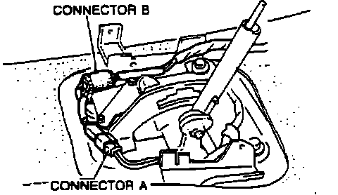
Fig. 8 Shift-lock Actuator Electrical Connectors:
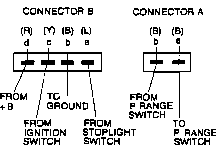
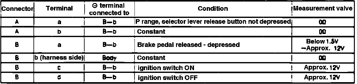
Fig. 9 Shift-lock Actuator Diagnostic Chart:
1. Remove upper panel from shift mechanism.
2. Shift selector lever to L range.
3. Remove selector lever knob, selector sleeve and indicator panel.
4. Disconnect hold switch connector Fig. 7, then shift selector lever to P range.
5. Turn ignition switch to ON position and test terminal voltages and continuity Figs. 8 and 9.
6. If tests are not as specified, repair wire harness and/or shift-lock actuator.