Unit Disassembly
TRANSMISSION UNIT (DISASSEMBLY)Preparation
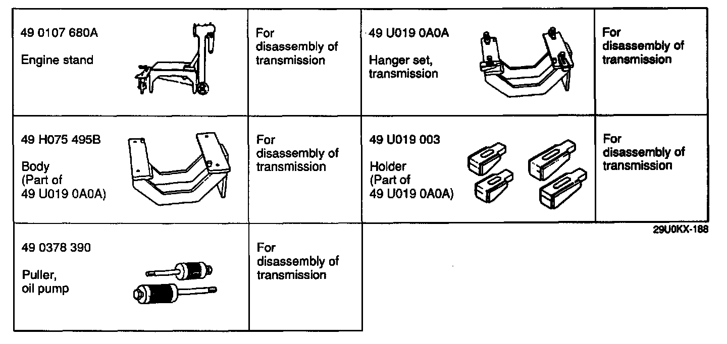
SST
Precaution
General Notes:
1. Disassemble the transmission in a clean area (clean work space) to prevent contaminants from entering into the mechanisms.
2. Inspect the individual transmission components in accordance with the QUICK DIAGNOSIS CHART during disassembly.
3. Use only plastic hammers when applying force to separate the light alloy case joints.
4. Never use rags during disassembly; they may leave particles that can clog fluid passages.
5. Several parts resemble one another; organize them so that they do not get mixed up.
6. Disassemble the control valve assembly and thoroughly clean it when the clutch or brake band has burned out or when the ATF has degenerated.
Cleaning Notes:
1. Clean the transmission exterior thoroughly with a steam cleaner or cleaning solvent, or both, before disassembly.
WARNING: Using compressed air can cause dirt and other particles to fly out, causing injury to the eyes. Wear protective eye wear whenever using compressed air.
2. Clean the removed parts with cleaning solvent, and dry with compressed air. Clean out all holes and passages with compressed air, and check that there are no obstructions.
Disassembly
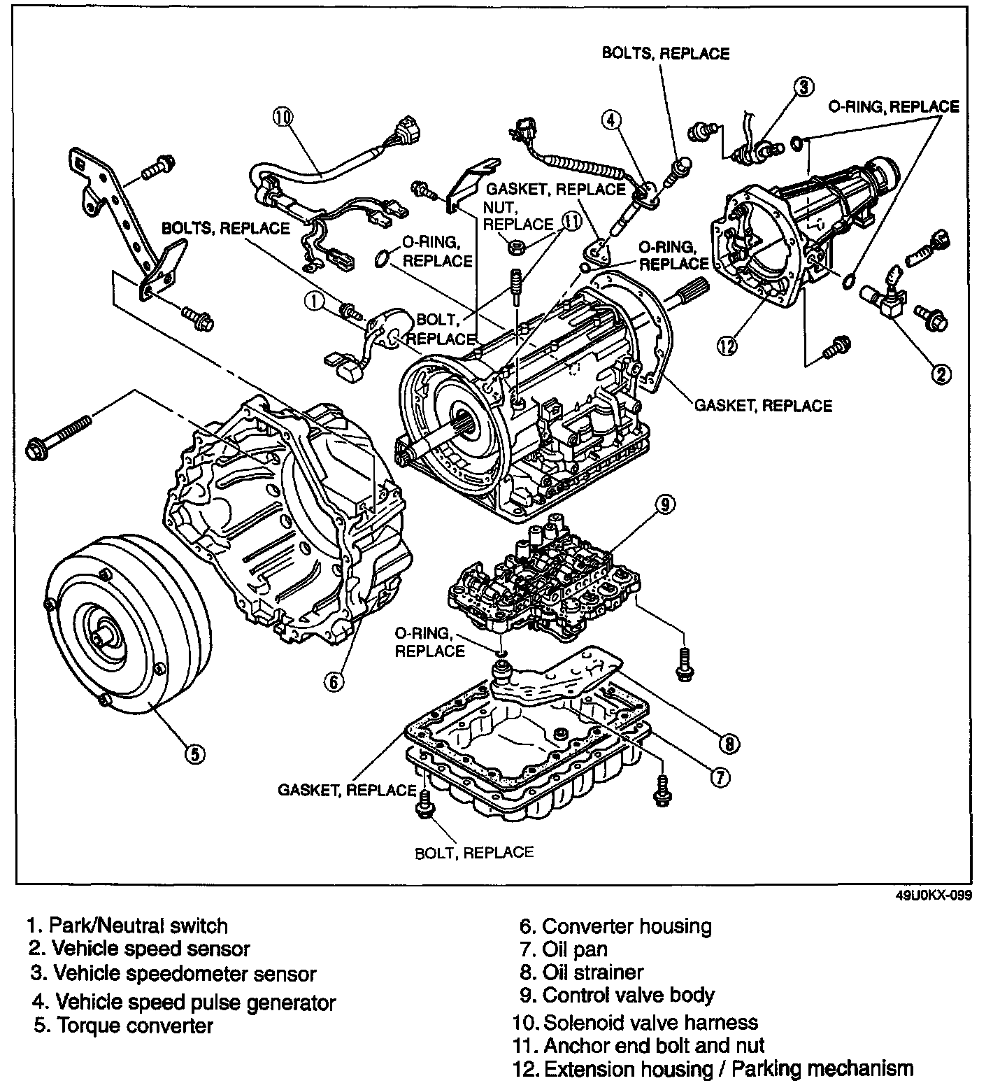
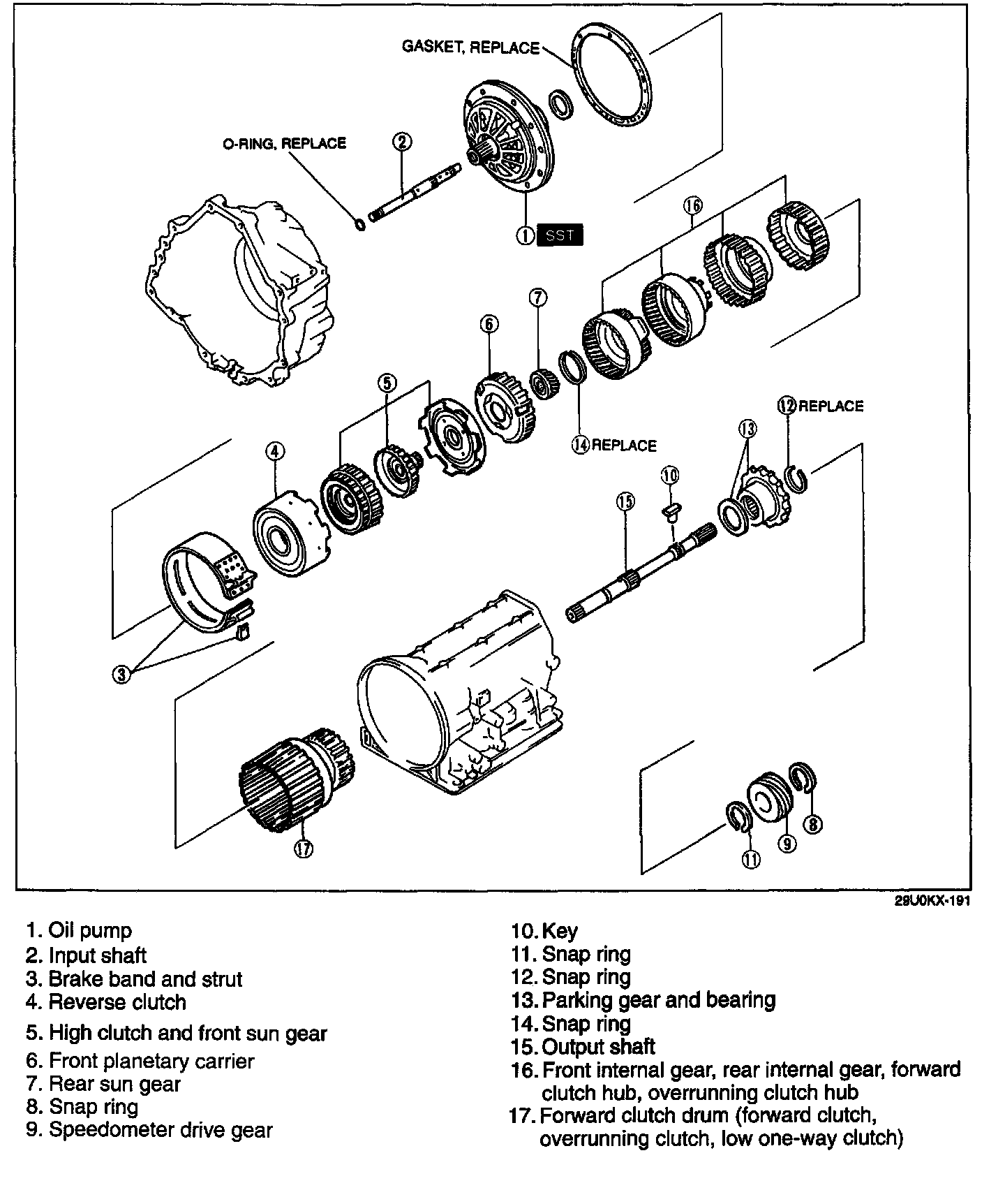
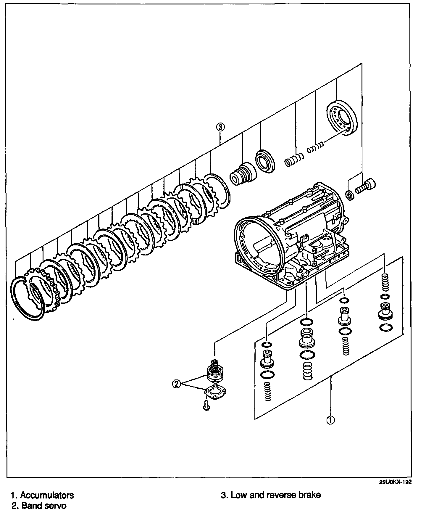
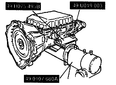
Disassemble in the order shown in the figures, referring to Disassembly Procedure.
Disassembly procedure
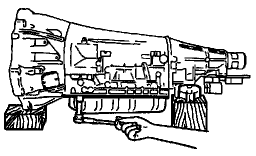
1. Place the transmission on wooden blocks under the converter housing and the extension housing.
2. Remove the oil pan and gasket.
3. Examine any material found in the pan or on the magnet to determine the condition of the transmission.
Clutch facing material ...... Drive plate and brake band wear
Steel (magnetic) ...... Bearing, gear, and driven plate wear
Aluminum (nonmagnetic) ...... Bushings or aluminum parts wear
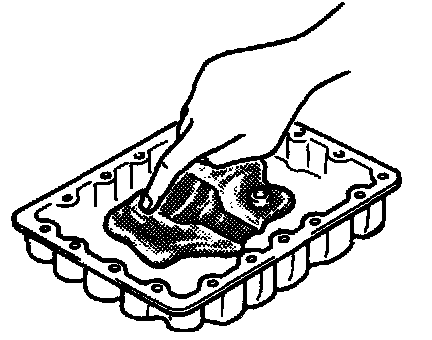
If large amounts of material are found in the oil pan, replace the torque converter.
4. Install the oil pan with a few bolts to protect the control valve body.
5. Remove the connector bracket from the transmission case.
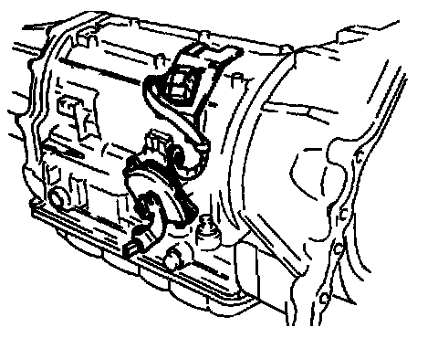
6. Remove the park/neutral switch.
7. Disconnect the harness from the connector bracket.
8. Remove the connector bracket from the converter housing.
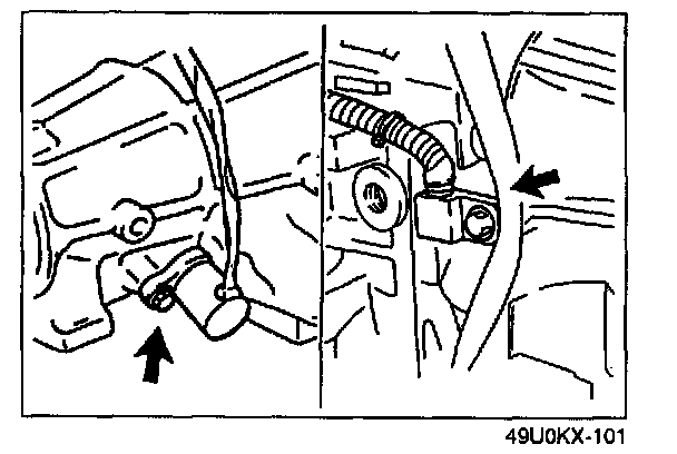
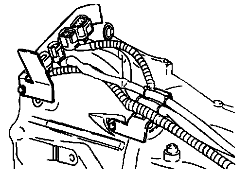
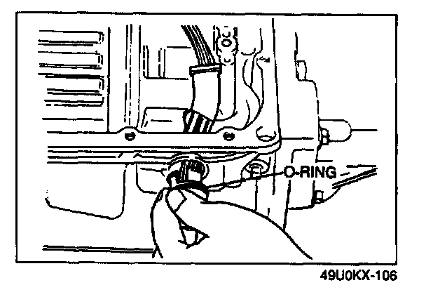
9. Remove the vehicle speedometer sensor.
10. Remove the O-ring from vehicle speedometer sensor.
11. Remove the vehicle speed sensor.
12. Remove the O-ring from vehicle speed sensor.
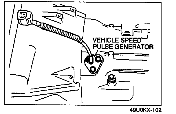
13. Remove the vehicle speed pulse generator and gasket from the transmission case.
14. Remove the O-ring from the vehicle speed pulse generator.
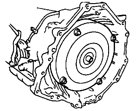
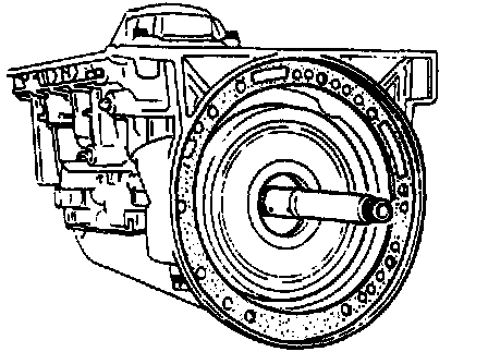
15. Remove the torque converter, and immediately turn it so that the hole faces upward. This will help to keep any remaining fluid from spilling.
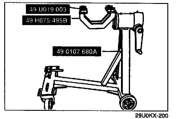
16. Assemble the SST as shown.
17. Mount the transmission to the SST.
18. Remove the oil pan, gasket, and magnet.
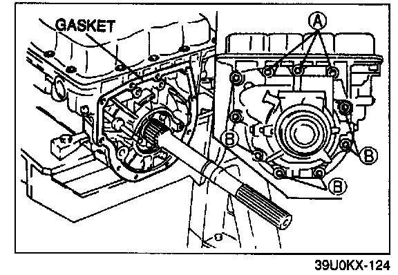
19. Remove the extension housing and gasket.
Bolt length (measured from below bolt head)
A: 30 mm {1.181 in}
B: 45 mm {1.772 in)
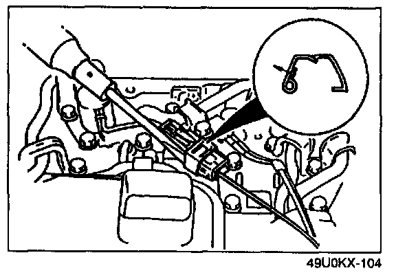
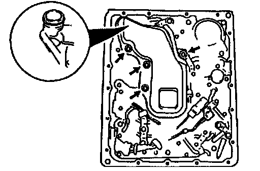
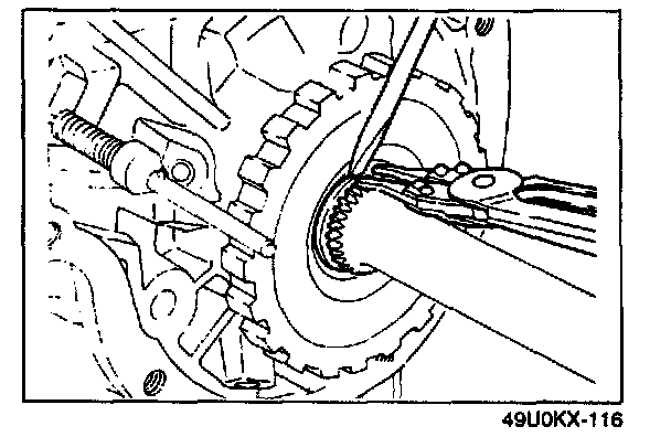
20. Remove the clip by carefully prying with a small flathead screwdriver.
21. Remove the lockup solenoid valve connector.
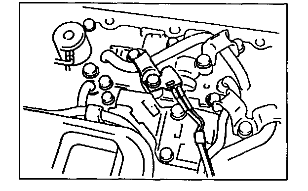
22. Remove the ATF thermosensor.
Bolt length (measured from below bolt head): 45 mm {1.772 in}
23. Remove the oil strainer.
Bolt length (measured from below bolt head): 50 mm {1.969 in}
24. Remove the O-ring from the oil strainer.
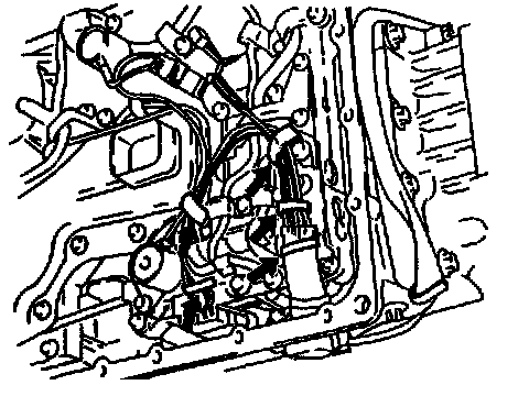
25. Separate the solenoid valve harness from the harness clip.
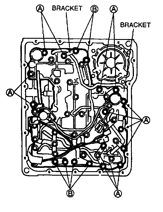
26. Remove bolts A and B and the brackets shown in the figure.
Bolt length (measured from below bolt head)
A: 33 mm {1.299 in}
B: 45 mm {1.772 in}
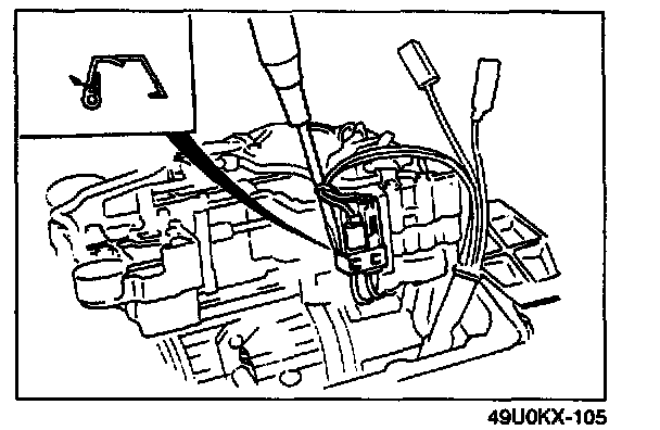
27. Remove the clip by carefully prying with a small flathead screwdriver.
28. Disconnect the solenoid valve connectors.
29. Remove the control valve body.
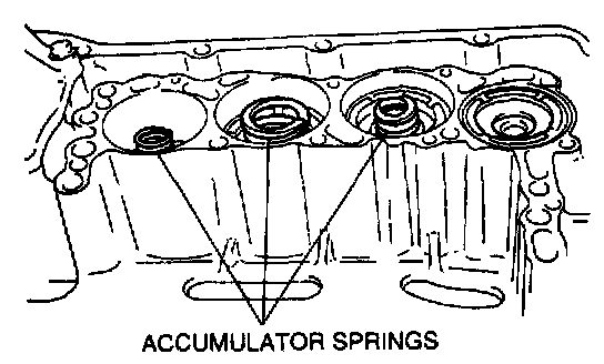
30. Remove the accumulator springs.
31. Remove the solenoid connector from the transmission case.
32. Remove the O-ring from the solenoid valve harness.
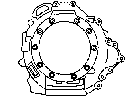
33. Remove the converter housing from the transmission case.
CAUTION: The converter housing is made of aluminum, and is therefore easily dented and scratched by metal tools. When removing old sealant, do not gouge or strike the sealing surface of the converter housing.
34. Clean the sealant from the converter housing.
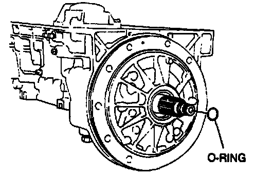
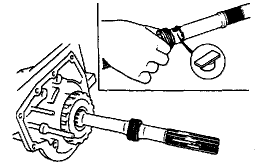
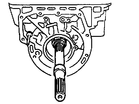
35. Remove the O-ring from the input shaft.
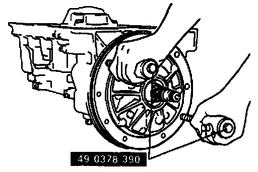
36. Install the SST to the oil pump.
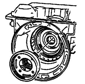
37. Slowly remove the oil pump from the transmission case by evenly sliding the weights of the SST.
38. Remove the SST from the oil pump.
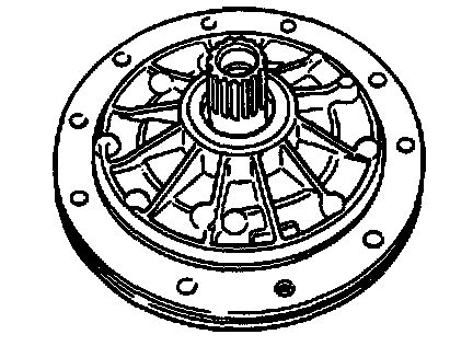
39. Clean the sealant from the oil pump housing, being careful not scratch or dent the machined surfaces.
40. Remove the oil pump gasket.
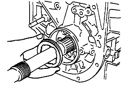
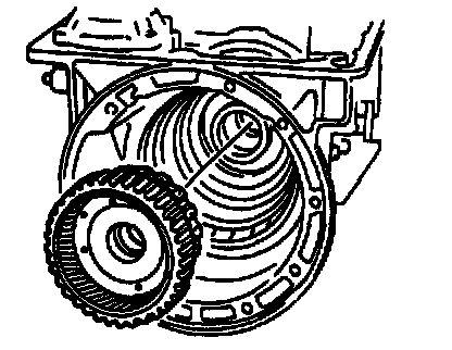
41. Pull out the input shaft while holding the reverse clutch drum.
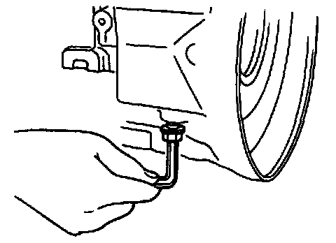
42. While holding the anchor end bolt, loosen the locknut.
43. Remove the anchor end bolt.
44. Clean the sealant from the case threads.
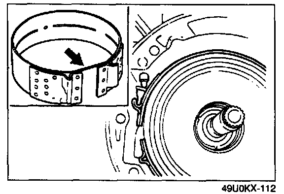
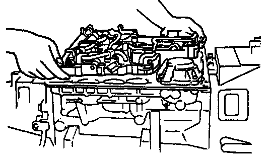
45. Remove the brake band and hold it together with a piece of wire as shown in the figure.
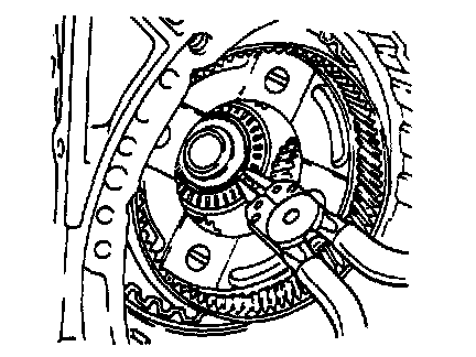
46. Remove the band strut.
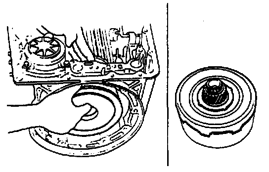
47. Remove the reverse clutch, high clutch, and front sun gear assembly from the transmission case.
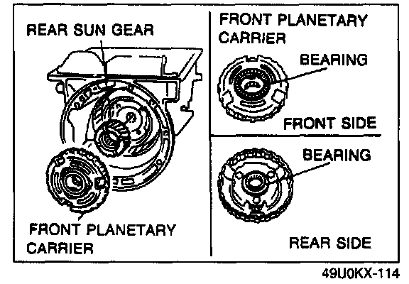
48. Remove the front planetary carrier, bearings, and rear sun gear.
Inspect the following and replace as necessary.
1. Front planetary carrier
Inspect gear teeth for damage, wear, and cracks.
Check for rough rotation of pinion gears.
2. Rear sun gear
Inspect gear teeth for damage, wear, and cracks.
3. Bearing
Inspect for damage and rough rotation.
49. Remove the rear snap ring and the speedometer drive gear.
50. Remove the key and the front snap ring.
51. Remove the snap ring from the output shaft.
52. Remove the parking gear.
53. Remove the bearing from the rear of the transmission case.
Inspect for damage and rough rotation, and replace as necessary.
54. Push the output shaft slightly forward and remove the snap ring from the output shaft.
55. Slide out the output shaft from the rear of the transmission case.
56. Remove the front internal gear (integrated with rear planetary carrier).
57. Remove the rear internal gear, forward clutch hub, and overrunning clutch hub assembly.
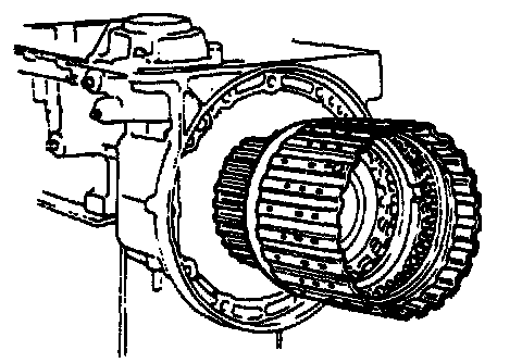
58. Remove the forward clutch drum (forward clutch, overrunning clutch, and low one-way clutch) assembly.