Procedures For Determining the Location of A Malfunction (Multiplex Communication System)
PROCEDURES FOR DETERMINING THE LOCATION OF A MALFUNCTION [MULTIPLEX COMMUNICATION SYSTEM]HS-CAN
System Wiring Diagram:

System Wiring Diagram
PCM
1. Inspect the display of DTC U0101, U0129, U0155 and/or U0300 using the M-MDS. (See DTC TABLE [MULTIPLEX COMMUNICATION SYSTEM]) Diagnostic Trouble Code Descriptions
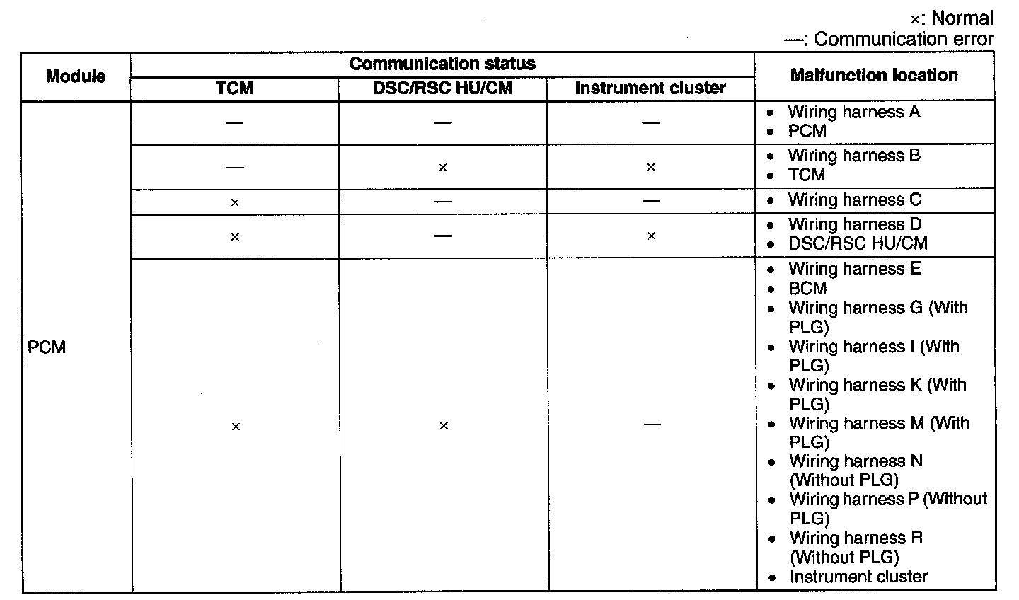
2. Referring to the following table, determine the malfunctioning part of the CAN system.
TCM
1. Inspect the display of DTC U0100, U0121, U0140 and/or U0415 using the M-MDS. (See DTC TABLE [MULTIPLEX COMMUNICATION SYSTEM]) Diagnostic Trouble Code Descriptions
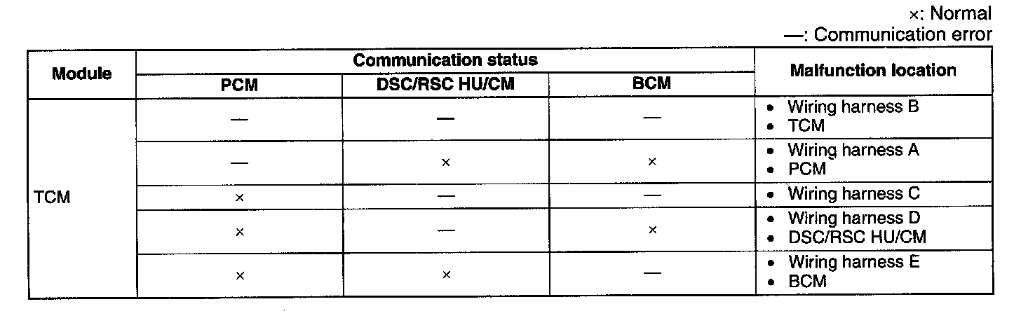
2. Referring to the following table, determine the malfunctioning part of the CAN system.
DSC/RSC HU/CM
1. Inspect the display of DTC U0100, U0140, U0155 and/or U2023 using the M-MDS. (See DTC TABLE [MULTIPLEX COMMUNICATION SYSTEM]) Diagnostic Trouble Code Descriptions
CAUTION:
- You may want to check which unit is malfunctioning according to Freeze Frame Data. "Electrical" > "IC Service Function" > "Freeze Frame Data" This function is supported on IDS, not PDS.
- DTC U2023 may not be cleared during engine starting even if DTC clearing is done using the M- MDS. When clearing DTC U2023, execute with the ignition switch in the ON position (Engine off).
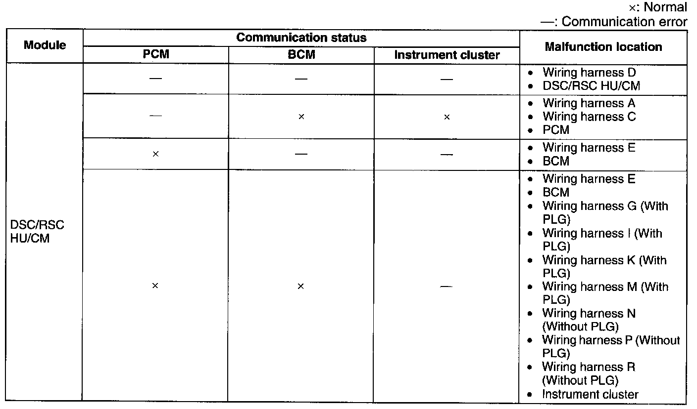
2. Referring to the following table, determine the malfunctioning part of the CAN system.
BCM
NOTE: There is no DTC in the BCM that determines signal quality between it and the other module. Due to this, determine the malfunction location using the DTC on the other module side.
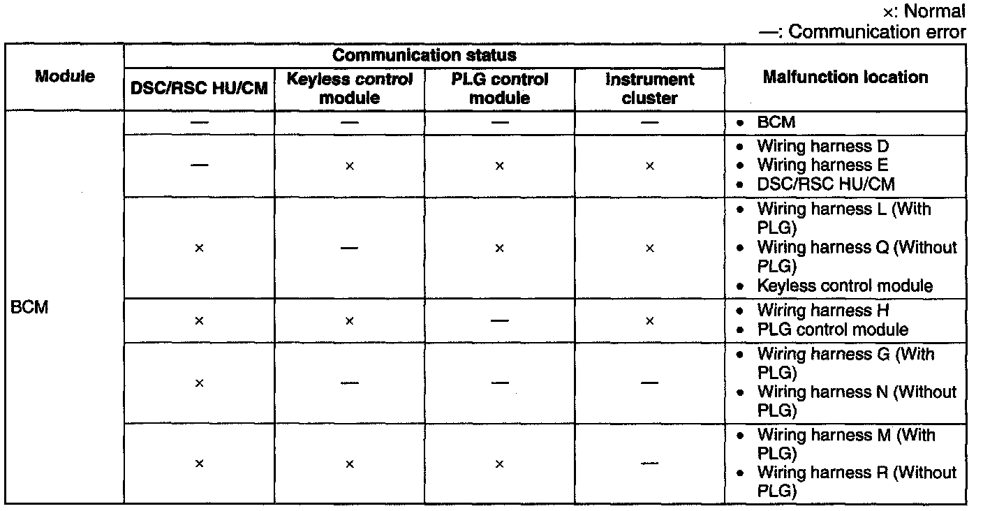
1. Referring to the following table, determine the malfunctioning part of the CAN system.
AWD Control Module
1. Inspect the display of DTC U0100, U0101, U0121 and/or U0155 using the M-MDS. (See DTC TABLE [MULTIPLEX COMMUNICATION SYSTEM]) Diagnostic Trouble Code Descriptions
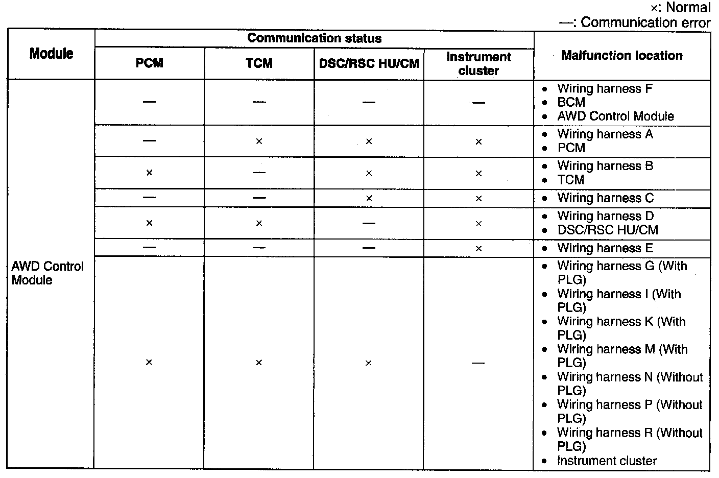
2. Referring to the following table, determine the malfunctioning part of the CAN system.
PLG Control Module
1. Inspect the display of DTC U0100, U0101, U140, U0155 and/or U0214 using the M-MDS. (See DTC TABLE [MULTIPLEX COMMUNICATION SYSTEM]) Diagnostic Trouble Code Descriptions
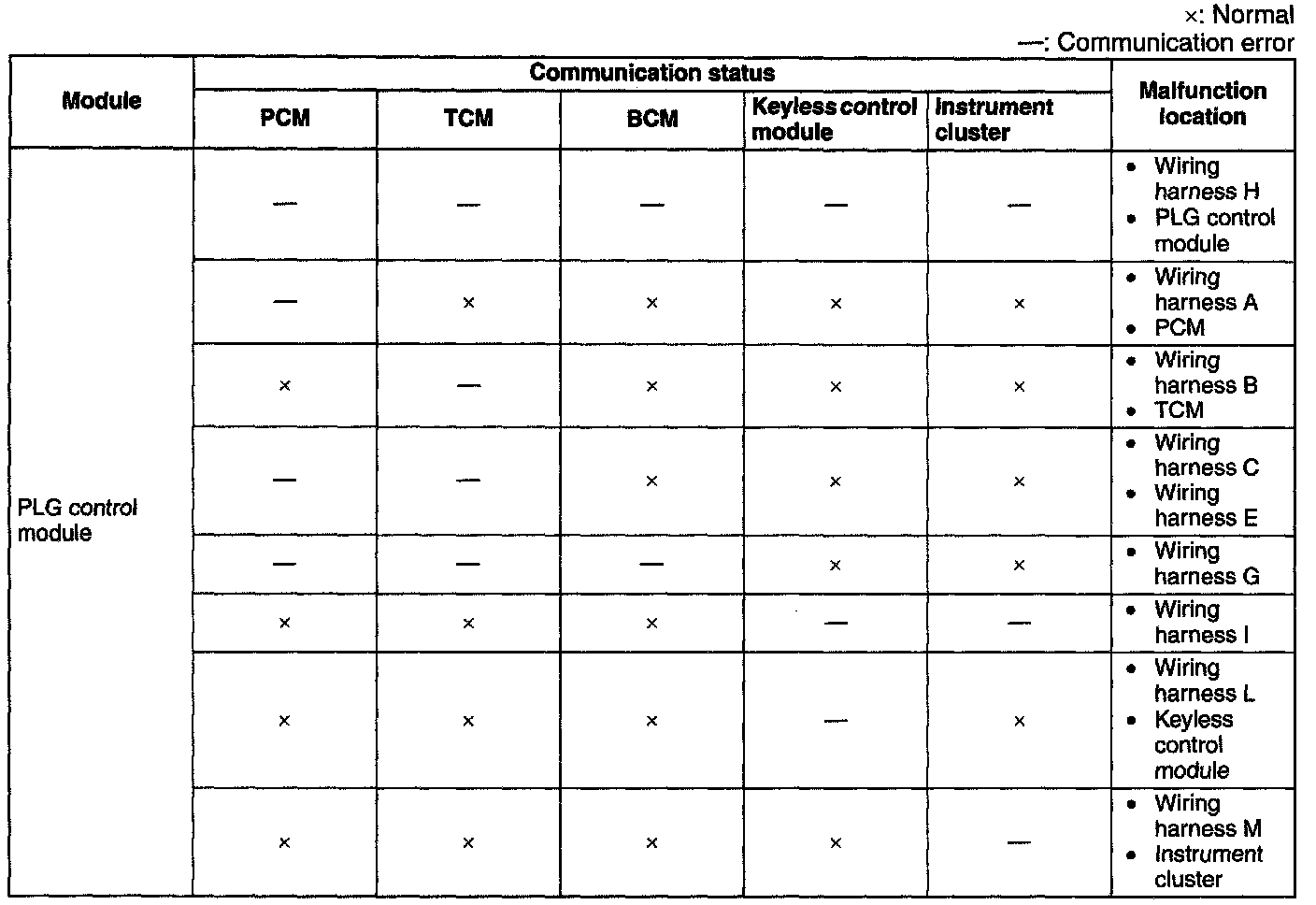
2. Referring to the following table, determine the malfunctioning part of the CAN system.
SAS Control Module
1. Inspect the display of DTC U0100 and/or U0155 using the M-MDS. (See DTC TABLE [MULTIPLEX COMMUNICATION SYSTEM]) Diagnostic Trouble Code Descriptions
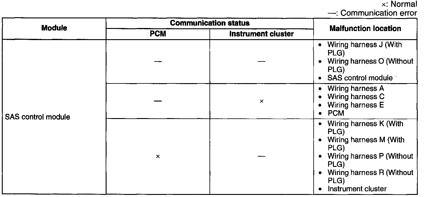
2. Referring to the following table, determine the malfunctioning part of the CAN system.
Keyless Control Module
1. Inspect the display of DTC U0100, U0140, U0323 and/or U2023 using the M-MDS. (See DTC TABLE [MULTIPLEX COMMUNICATION SYSTEM]) Diagnostic Trouble Code Descriptions
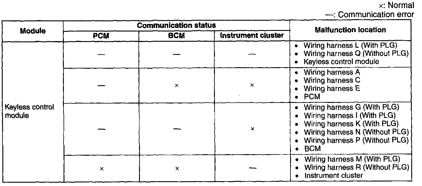
2. Referring to the following table, determine the malfunctioning part of the CAN system.
Instrument Cluster
1. Inspect the display of DTC U0100, U0101, U0114, U0121, U0140, U0151 and/or U0214 using the M-MDS. (See DTC TABLE [MULTIPLEX COMMUNICATION SYSTEM]) Diagnostic Trouble Code Descriptions
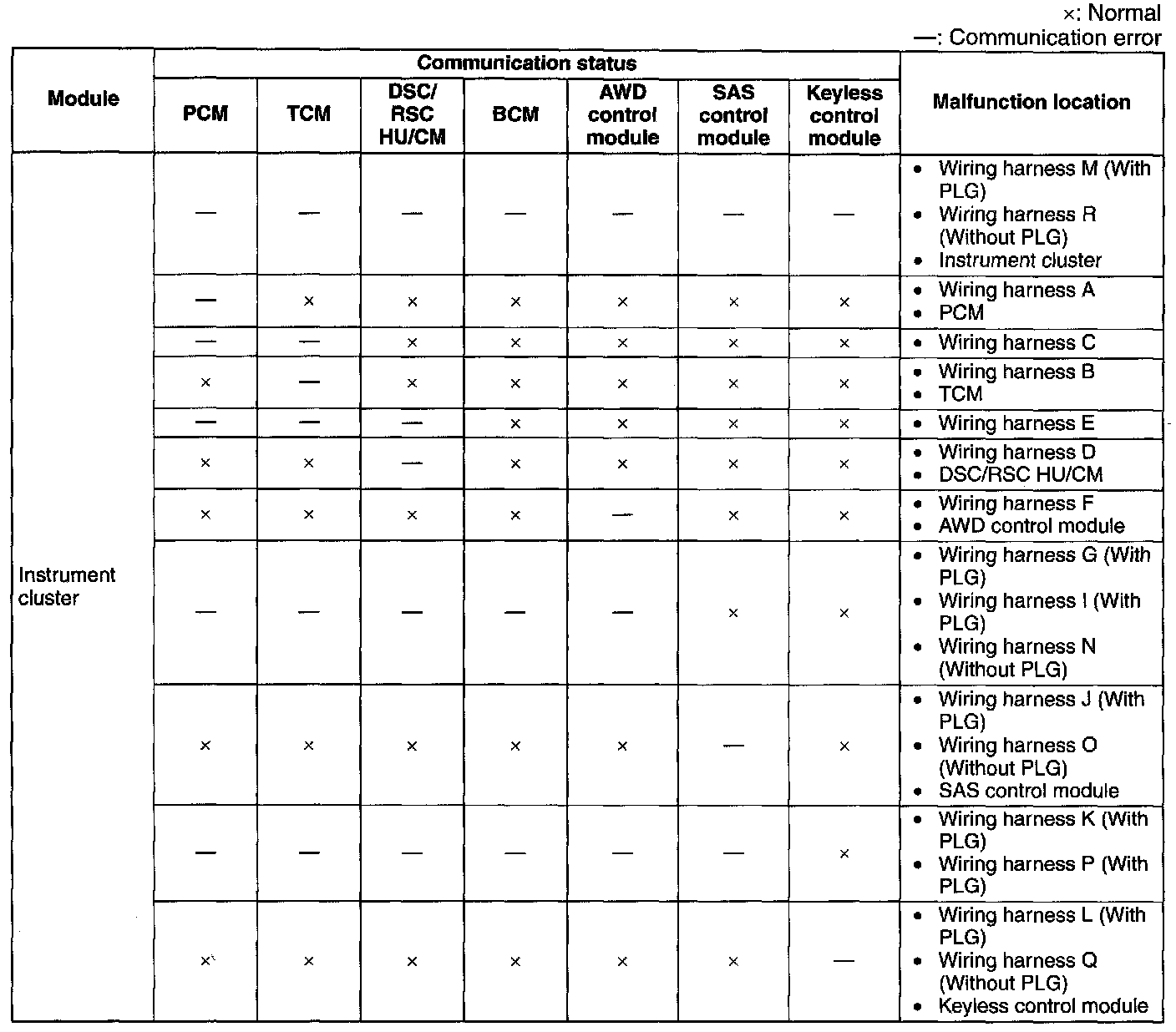
2. Referring to the following table, determine the malfunctioning part of the CAN system.
MS-CAN
System Wiring Diagram:
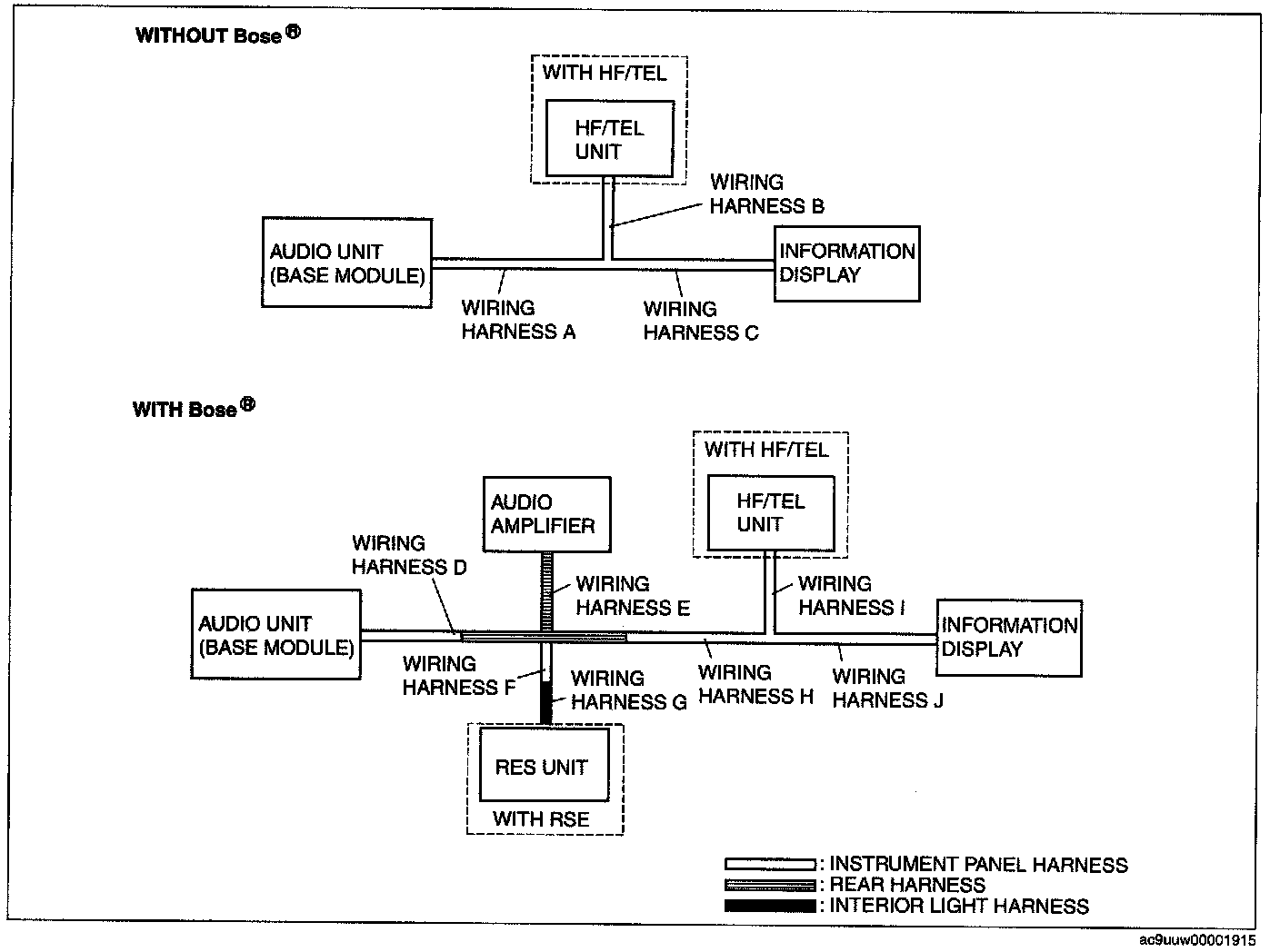
System Wiring Diagram
Audio Unit (Base Module)
1. Inspect the display of DTC 23:Er11 (Touch panel type) using starting procedure for on-board diagnostic test mode. (See STARTING PROCEDURE FOR ON-BOARD DIAGNOSTIC TEST MODE [AUDIO (TOUCH PANEL TYPE AUDIO)]
2. Referring to the following table, determine the malfunctioning part of the CAN system.
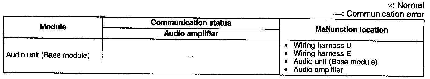
Audio Amplifier
NOTE: There is no DTC in the audio amplifier that determines signal quality between it and the audio unit (Base module). Due to this, determine the malfunction location using the DTC on the information display.

1. Referring to the following table, determine the malfunctioning part of the CAN system.
Information display
1. Inspect the display of DTC U0184 using the input/output check mode. (See INFORMATION DISPLAY INPUT/OUTPUT CHECK MODE.) Reading and Clearing Diagnostic Trouble Codes
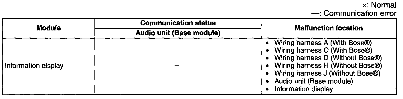
2. Referring to the following table, determine the malfunctioning part of the CAN system.
Repair Procedure
1. Inspect the connector of malfunctioning module.
- If there is any malfunction, repair or replace the connector.
2. Inspect the malfunctioning wiring harnesses as follow.
- If there is any malfunction, repair or replace the wiring harnesses.
- If there is no malfunction, replace the malfunctioning module.
- Short to GND
- Short to power supply
- Twisted pair short each other
- Open circuit
3. Make sure to reconnect all disconnected connectors.
4. Clear the CAN system related DTCs using the M-MDS.
5. Verify if the CAN system related DTCs are displayed using the M-MDS.
- If the same following DTCs are present, replace the malfunctioning module.
- U0073 (TCM, DSC/RSC HU/CM, BCM, AWD control module, SAS control module, keyless control module, instrument cluster)
- U2516 (Information display)
- 26:Er81, CAN Bus (HF/TEL unit)
- If other DTC is present, perform the appropriate DTC inspection. (See DTC TABLE [MULTIPLEX COMMUNICATION SYSTEM]) Diagnostic Trouble Code Descriptions