 |
arnffw00000870
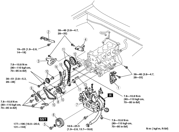
TIMING CHAIN REMOVAL/INSTALLATION [G6]
id011095801000
1. Disconnect the negative battery cable.
2. Remove the generator. (See GENERATOR REMOVAL/INSTALLATION [G6].)
3. Remove the P/S oil pump with the oil hose still connected. Position the P/S oil pump so that it is out of the way. (See POWER STEERING OIL PUMP REMOVAL/INSTALLATION [G6].)
4. Remove the A/C compressor with the pipe connected. Position the A/C compressor so that it is out of the way.
5. Remove the cylinder head. (See CYLINDER HEAD GASKET REPLACEMENT [G6].)
6. Remove the water pump. (See WATER PUMP REMOVAL/INSTALLATION [G6].)
7. Remove the oil pan. (See OIL PAN REMOVAL/INSTALLATION [G6].)
8. Disconnect the oil strainer stay.
9. Remove in the order indication in the table.
10. Install in the reverse order of the removal.
11. Start the engine and inspect for engine oil and engine coolant leakage.
arnffw00000870
|
|
1
|
A/C compressor bracket
|
|
2
|
Generator strap
|
|
3
|
P/S oil pump bracket
|
|
4
|
Generator bracket
|
|
5
|
Pulley lock bolt
|
|
6
|
Crankshaft pulley
|
|
7
|
Chain cover
|
|
8
|
Spacer
|
|
9
|
Balancer chain guide
|
|
10
|
Balancer chain, idler sprocket
|
|
11
|
Timing chain, timing sprocket, camshaft sprocket
|
|
12
|
Chain adjuster
|
|
13
|
Key
|
|
14
|
Timing chain lever
|
|
15
|
Timing chain guide
|
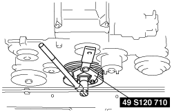
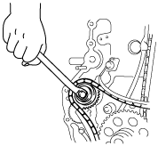
Pulley Lock Bolt Removal/Installation Note
1. Hold the crankshaft using the SST.
absggw00000044
|
Timing Chain Lever Installation Note
1. Install the chain lever and verify that it moves smoothly in the direction indicated.
absggw00000045
|
Chain Adjuster Installation Note
1. Push the chain adjuster sleeve in (toward the left) and insert the pin as shown into the lever to hold the sleeve.
absggw00000046
|
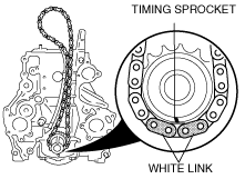
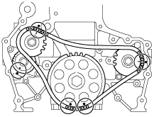
Timing Chain, Timing Sprocket, Camshaft Sprocket Installation Note
1. Install the timing chain and timing sprocket so that the white link of the timing chain is aligned with the timing mark of the timing sprocket as shown.
absggw00000047
|
2. Assemble the camshaft sprocket to the timing chain so that the timing mark of camshaft sprocket is aligned with the white link of timing chain as shown.
absggw00000048
|
3. Secure the camshaft sprocket and the timing chain with a wire to prevent disengagement.
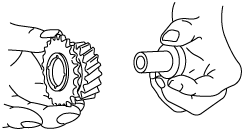
Balancer Chain, Idler Sprocket, Crankshaft Sprocket Installation Note
1. Install the crankshaft sprocket as shown.
absggw00000049
|
2. Assemble the idler sprocket on the idler shaft.
absggw00000050
|
3. Set the balancer chain on the idler sprocket so that the timing mark of the idler sprocket is aligned with the brown link of the balancer chain as shown.
absggw00000051
|
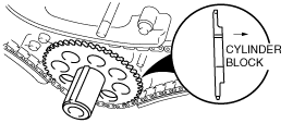
4. Install the balancer chain so that the five alignment marks on the chain, sprocket and cylinder block align, and attach the idler sprocket to the cylinder block.
absggw00000052
|
5. Hand-tighten the idler sprocket lock bolt.
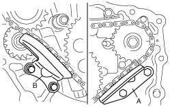
Balancer Chain Guide Installation Note
1. Install the chain guide A and B.
absggw00000053
|
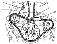
2. Install the chain guide C, and tighten the bolt D and hand-tighten the adjusting bolt E.
absggw00000054
|
3. Tighten the idler sprocket look bolt.
absggw00000055
|
4. Loosen the chain guide C by adjusting bolt E.
5. Push the chain guide C with a force of 49 N {5.0 kgf, 11 lbf} in the direction of the arrow, then pull back the chain guide 3.2—3.8 mm {0.13—0.14 in} and tighten the adjusting bolt E.
absggw00000056
|
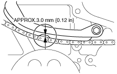
6. Measure the timing chain slack.
absggw00000057
|