 |
absggw00000706
ON-BOARD DIAGNOSIS
id040200805500
On-Board Diagnostic (OBD) Test Description
Read/clear diagnostic results
PID/Data monitor and record
Active command modes
Reading DTCs Procedure
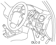
1. Connect the M-MDS to the DLC-2.
absggw00000706
|
2. After the vehicle is identified, select the following items from the initialization screen of the M-MDS.
3. Verify the DTC according to the directions on the screen.
4. After completion of repairs, clear all DTCs stored in the ABS HU/CM. (See Clearing DTCs Procedures.)
Clearing DTCs Procedures
1. Connect the M-MDS to the DLC-2.
absggw00000706
|
2. After the vehicle is identified, select the following items from the initialization screen of the M-MDS.
3. Verify the DTC according to the directions on the screen.
4. Press the clear button on the DTC screen to clear the DTC.
5. Turn the ignition switch to the LOCK position.
6. Turn the ignition switch to the ON position and wait for 5 s or more.
7. Perform DTC inspection. (See Reading DTCs Procedure.)
8. Verify that no DTCs are displayed.
PID/Data Monitor and Record Procedure
1. Connect the M-MDS to the DLC-2.
absggw00000706
|
2. After the vehicle is identified, select the following items from the initialization screen of the M-MDS.
3. Select the applicable PID from the PID table.
4. Verify the PID data according to the directions on the screen.
Active Command Modes Procedure
1. Connect the M-MDS to the DLC-2.
absggw00000706
|
2. After the vehicle is identified, select the following items from the initialization screen of the M-MDS.
3. Select the active command modes from the PID table.
4. Perform the active command modes, inspect the operations for each parts.
DTC Table
|
DTC |
System malfunction location |
Page |
|---|---|---|
|
B1317
|
Power supply system
|
(See DTC B1317, B1318.)
|
|
B1318
|
Power supply system
|
(See DTC B1317, B1318.)
|
|
B1342
|
ABS HU/CM system
|
(See DTC B1342.)
|
|
B1484
|
Brake switch system
|
(See DTC B1484.)
|
|
C1095
|
Pump motor, motor relay system
|
(See DTC C1095, C1096.)
|
|
C1096
|
Pump motor, motor relay system
|
(See DTC C1095, C1096.)
|
|
C1145
|
RF ABS wheel-speed sensor system
|
|
|
C1155
|
LF ABS wheel-speed sensor system
|
|
|
C1165
|
RR ABS wheel-speed sensor system
|
|
|
C1175
|
LR ABS wheel-speed sensor system
|
|
|
C1186
|
Fail-safe relay system
|
(See DTC C1186.)
|
|
C1194
|
LF outlet solenoid valve system
|
|
|
C1198
|
LF inlet solenoid valve system
|
|
|
C1202
|
Rear outlet solenoid valve system
|
|
|
C1206
|
Rear inlet solenoid valve system
|
|
|
C1210
|
RF outlet solenoid valve system
|
|
|
C1214
|
RF inlet solenoid valve system
|
|
|
C1222
|
ABS wheel-speed sensor (slip monitor) system
|
(See DTC C1222.)
|
|
C1233
|
LF ABS wheel-speed sensor/ABS sensor rotor system
|
|
|
C1234
|
RF ABS wheel-speed sensor/ABS sensor rotor system
|
|
|
C1235
|
RR ABS wheel-speed sensor/ABS sensor rotor system
|
|
|
C1236
|
LR ABS wheel-speed sensor/ABS sensor rotor system
|
|
|
C1414
|
Incorrect ABS HU/CM installed
|
(See DTC C1414.)
|
|
C1730*
|
G sensor system
|
(See DTC C1730, C1949, C1950.)
|
|
C1949*
|
G sensor system
|
(See DTC C1730, C1949, C1950.)
|
|
C1950*
|
G sensor system
|
(See DTC C1730, C1949, C1950.)
|
PID/DATA Monitor Table
|
PID name (definition) |
Unit/Condition |
Operation condition (reference) |
Action |
ABS HU/CM terminal |
|---|---|---|---|---|
|
ABS_LAMP
(ABS warning light driver output state)
|
On/Off
|
• ABS warning light is illuminated: ON
• ABS warning light is not illuminated: Off
|
Inspect the ABS warning light.
|
S
|
|
ABS_VOLT
(System battery voltage value)
|
V
|
• Ignition switch or engine switch at ON: Approx. 12.2 V
• Idling: Approx. 14.1 V
|
Inspect the power supply circuit.
(See ABS HU/CM SYSTEM INSPECTION.)
|
J
|
|
ACCLMTR*
(Forward-G sensor input)
|
G
|
• Vehicle is stopped or driving at a constant speed: 0 G
• Cornering to left: Changes between 0 G and 1.5 G
• Cornering to right: Changes between 0 G and -1.5 G
|
Inspect the G sensor.
(See G SENSOR INSPECTION.)
|
P
|
|
BOO_ABS
(Brake pedal switch input)
|
On/Off
|
• Brake pedal depressed: On
• Brake pedal released: Off
|
Inspect the brake switch.
(See BRAKE SWITCH INSPECTION.)
|
N
|
|
CCNTABS
(Number of continuous codes)
|
—
|
• DTCs detected:
1—255
• No DTCs detected: 0
|
Perform the DTC inspection.
|
—
|
|
PMP_MOTOR
(Pump motor output state)
|
On/Off
|
• Pump motor activated: On
• Pump motor not activated: Off
|
Inspect the ABS HU/CM.
(See ABS HU/CM INSPECTION.)
|
—
|
|
RLY_PMP
(Pump motor relay output state)
|
On/Off
|
• Relay activated: On
• Relay not activated: Off
|
Inspect the ABS HU/CM.
(See ABS HU/CM INSPECTION.)
|
—
|
|
RLY_VLV
(Solenoid valve relay output state)
|
On/Off
|
• Solenoid valve relay is
activated: On
• Solenoid valve relay is deactivated: Off
|
Inspect ABS HU/CM.
(See ABS HU/CM INSPECTION)
|
—
|
|
V_LF_INL
(Left front inlet solenoid valve output state)
|
On/Off
|
• Solenoid valve activated: On
• Solenoid valve not activated: Off
|
Inspect the ABS HU/CM.
(See ABS HU/CM INSPECTION.)
|
—
|
|
V_LF_OTL
(Left front outlet solenoid valve output state)
|
On/Off
|
• Solenoid valve activated: On
• Solenoid valve not activated: Off
|
Inspect the ABS HU/CM.
(See ABS HU/CM INSPECTION.)
|
—
|
|
V_RF_INL
(Right front inlet solenoid valve output state)
|
On/Off
|
• Solenoid valve activated: On
• Solenoid valve not activated: Off
|
Inspect the ABS HU/CM.
(See ABS HU/CM INSPECTION.)
|
—
|
|
V_RF_OTL
(Right front outlet solenoid valve output state)
|
On/Off
|
• Solenoid valve activated: On
• Solenoid valve not activated: Off
|
Inspect the ABS HU/CM.
(See ABS HU/CM INSPECTION.)
|
—
|
|
V_Rear_ INL
(Rear inlet solenoid valve output state)
|
On/Off
|
• Solenoid valve activated: On
• Solenoid valve not activated: Off
|
Inspect the ABS HU/CM.
(See ABS HU/CM INSPECTION.)
|
—
|
|
V_Rear_OTL
(Rear outlet solenoid valve output state)
|
On/Off
|
• Solenoid valve activated: On
• Solenoid valve not activated: Off
|
Inspect the ABS HU/CM.
(See ABS HU/CM INSPECTION.)
|
—
|
|
WSPD_LF
(Left front ABS wheel-speed sensor input)
|
KPH, MPH
|
• Vehicle stopped: 0 KPH, 0 MPH
• Vehicle running: Vehicle speed
|
Inspect the ABS wheel-speed sensor.
|
E, F
|
|
WSPD_LR
(Left rear ABS wheel-speed sensor input)
|
KPH, MPH
|
• Vehicle stopped: 0 KPH, 0 MPH
• Vehicle running: Vehicle speed
|
Inspect the ABS wheel-speed sensor.
|
I, G
|
|
WSPD_RF
(Right front ABS wheel-speed sensor input)
|
KPH, MPH
|
• Vehicle stopped: 0 KPH, 0 MPH
• Vehicle running: Vehicle speed
|
Inspect the ABS wheel-speed sensor.
|
O, M
|
|
WSPD_RR
(Right rear ABS wheel-speed sensor input)
|
KPH, MPH
|
• Vehicle stopped: 0 KPH, 0 MPH
• Vehicle running: Vehicle speed
|
Inspect the ABS wheel-speed sensor.
|
L, K
|
Active Command Modes Table
|
Command name |
Output part |
Operation |
Operating condition |
|---|---|---|---|
|
PMP_MOTOR
|
Pump motor
|
On/Off
|
Ignition switch or engine switch at ON
|
|
V_LF_INL
|
LF inlet solenoid valve
|
||
|
V_LF_OTL
|
LF outlet solenoid valve
|
||
|
V_Rear_INL
|
Rear inlet solenoid valve
|
||
|
V_Rear_OTL
|
Rear outlet solenoid valve
|
||
|
V_RF_INL
|
RF inlet solenoid valve
|
||
|
V_RF_OTL
|
RF outlet solenoid valve
|