DTC P0705, P0708, P1702, P1704, P1705 [5R55S]


id0502c1814500

DTC P0705

Digital transmission range (TR) sensor circuit malfunction (invalid bit pattern)

DTC P0708

Digital transmission range (TR) sensor circuit malfunction (TR3A circuit open)

DTC P1702

Digital transmission range (TR) sensor circuit intermittent

DTC P1704

Digital transmission range (TR) sensor circuit not indicating P or N position during on-board diagnostic

DTC P1705

Digital transmission range (TR) sensor circuit not indicating P or N position during on-board diagnostic

DETECTION CONDITION
•  P0705: Open circuit or short to ground in wiring harness between digital TR sensor terminal and TCM terminal or in digital TR sensor internal circuit (invalid bit pattern)
•  P0708: Open circuit in wiring harness between digital TR sensor and TCM terminal or in digital TR sensor internal circuit (TR3 circuit)
•  P1702: TCM cannot detect a signal from digital TR sensor
•  P1704: PID TR_D not indicating P or N position, digital TR sensor or selector cable misalignment
•  P1705: On-board diagnostic not performed in P or N position
POSSIBLE CAUSE
•  Digital TR sensor malfunction
•  Digital TR sensor or selector cable misadjustment
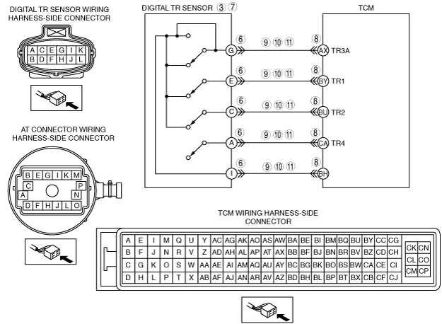
•  Short to ground in wiring harness between digital TR sensor terminal G and TCM terminal AX
•  Short to ground in wiring harness between digital TR sensor terminal E and TCM terminal BY
•  Short to ground in wiring harness between digital TR sensor terminal C and TCM terminal BU
•  Short to ground in wiring harness between digital TR sensor terminal A and TCM terminal CA
•  Short to ground in wiring harness between digital TR sensor terminal I and TCM terminal BH
•  Open circuit in wiring harness between digital TR sensor terminal G and TCM terminal AX
•  Open circuit in wiring harness between digital TR sensor terminal E and TCM terminal BY
•  Open circuit in wiring harness between digital TR sensor terminal C and TCM terminal BU
•  Open circuit in wiring harness between digital TR sensor terminal A and TCM terminal CA
•  Open circuit in wiring harness between digital TR sensor terminal I and TCM terminal BH
•  Short to power supply in wiring harness between digital TR sensor terminal G and TCM terminal AX
•  Short to power supply in wiring harness between digital TR sensor terminal E and TCM terminal BY
•  Short to power supply in wiring harness between digital TR sensor terminal C and TCM terminal BU
•  Short to power supply in wiring harness between digital TR sensor terminal A and TCM terminal CA
•  Short to power supply in wiring harness between digital TR sensor terminal I and TCM terminal BH
•  Damaged connectors between digital TR sensor and TCM
•  TCM malfunction

Diagnostic procedure

STEP

INSPECTION

ACTION

1
VERIFY FREEZE FRAME DATA HAS BEEN RECORDED
•  Has the FREEZE FRAME DATA been recorded?
Yes
Go to the next step.
No
Record the FREEZE FRAME DATA on the repair order, then go to the next step.
2
VERIFY RELATED SERVICE INFORMATION AVAILABILITY
•  Verify related Service Information availability.
•  Is any related Service Information available?
Yes
Perform repair or diagnosis according to the available Service Information.
•  If the vehicle is not repaired, go to the next step.
No
Go to the next step.
3
VERIFY DIGITAL TR SENSOR ALIGNMENT
•  Select the N position.
•  Turn the engine switch to the LOCK position.
•  Disconnect the selector cable from the manual lever.
•  Verify that the SST (307-351 (49 UN30 7351)) fits in the appropriate slots of digital TR sensor.
•  Is the digital TR sensor correctly adjusted?
Yes
Connect the selector cable to the manual lever, then go to the next step.
No
Adjust the digital TR sensor, then go to Step 12.
4
VERIFY SELECTOR CABLE ADJUSTMENT
•  Turn the engine switch to the ON position.
•  Verify that the selector cable is correctly adjusted.
•  Is the selector cable is correctly adjusted?
Yes
Go to the next step.
No
Adjust the selector cable, then go to Step 12.
5
INSPECT ELECTRICAL SYSTEM OPERATION
•  Connect the IDS/PDS to DLC-2.
•  Access TR_D and TR_V PIDs.
•  Move the selector lever into each range and position (P, R, N, D, 3, 2, 1).
•  Observe the PIDs, TR D and TR V (vehicle-dependent) while wiggling wiring harness, tapping on sensor or driving the vehicle.
―  Use PIDs TR_D for DTCs P0705, P1704 and P1705.
―  Use PIDs TR_V for DTC P0708.
•  Are the PIDs within the specification?
Yes
Go to Step 12.
No
Go to the next step.
6
INSPECT DIGITAL TR SENSOR CONNECTOR FOR POOR CONNECTION
•  Turn the engine switch to the LOCK position.
•  Disconnect the digital TR sensor connector.
•  Inspect for poor connection (such as damaged/pulled-out pins, corrosion)
•  Is the connection normal?
Yes
Go to the next step.
No
Repair or replace connector and/or terminal, then go to Step 12.
7
INSPECT DIGITAL TR SENSOR
•  Inspect the digital TR sensor.
•  Is digital TR sensor normal?
Yes
Go to the next step.
No
Replace the digital TR sensor, then go to Step 12.
8
INSPECT TCM CONNECTOR FOR POOR CONNECTION
•  Disconnect the TCM connector.
•  Inspect for poor connection (such as damaged/pulled-out pins, corrosion).
•  Is the connection normal?
Yes
Go to the next step.
No
Repair or replace the connector and/or terminals, then go to Step 12.
9
INSPECT DIGITAL TR SENSOR CIRCUIT FOR SHORT TO GROUND
•  Inspect continuity between digital TR sensor terminals (wiring harness-side) and body ground.
―  G and body ground
―  E and body ground
―  C and body ground
―  A and body ground
―  I and body ground
•  Is there continuity?
Yes
Repair or replace the wiring harness, then go to Step 12.
No
Go to the next step.
10
INSPECT DIGITAL TR SENSOR CIRCUIT FOR SHORT TO POWER SUPPLY
•  Turn the engine switch to the ON position (engine off).
•  Inspect the voltage at digital TR sensor terminals G, E, C, A and I (wiring harness-side).
•  Is the voltage 0 V?
Yes
Go to the next step.
No
Repair or replace the wiring harness, then go to Step 12.
11
INSPECT DIGITAL TR SENSOR CIRCUIT FOR OPEN CIRCUIT
•  Inspect the following digital TR sensor terminals (wiring harness-side) and TCM terminals (wiring harness-side):
―  G and AX
―  E and BY
―  C and BU
―  A and CA
―  I and BH
•  Is there continuity?
Yes
Go to the next step.
No
Repair or replace the wiring harness, then go to the next step.
12
VERIFY TROUBLESHOOTING OF DTC P0705, P0708, P1702, P1704 OR P1705 COMPLETED
•  Make sure to reconnect all the disconnected connectors.
•  Clear the DTC from the memory using the IDS/PDS.
•  Perform the “After Repair Procedure”.
•  Is the same DTC present?
Yes
Replace the TCM, then go to the next step.
No
Go to the next step.
13
VERIFY DTCS
•  Are DTCs except for P0705, P0708, P1702, P1704 and P1705 output?
Yes
Go to the applicable DTC inspection.
No
DTC troubleshooting completed.