 |
absggw00001190
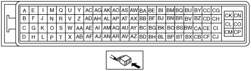
TCM INSPECTION [5R55S]
id0513c1250700
Terminal Voltage/Resistance Table (Reference)
absggw00001190
|
|
Terminal |
Signal |
Connected to |
Test Condition |
Voltage/Resistance |
Action |
|
|---|---|---|---|---|---|---|
|
A
|
TCC control solenoid control
|
TCC control solenoid
|
Inspect resistance between TCM terminals A and CK (wiring harness-side).
|
9—16 ohm
|
• Inspect the TCC control solenoid
• Inspect the related wiring harness
|
|
|
B
|
Shift solenoid A control
|
Shift solenoid A
|
Inspect resistance between TCM terminals B and CK (wiring harness-side).
|
16—45 ohm
|
• Inspect the shift solenoid A
• Inspect the related wiring harness
|
|
|
C
|
Shift solenoid B control
|
Shift solenoid B
|
Inspect resistance between TCM terminals C and CK (wiring harness-side).
|
16—45 ohm
|
• Inspect the shift solenoid B
• Inspect the related wiring harness
|
|
|
D
|
Shift solenoid D control
|
Shift solenoid D
|
Inspect resistance between TCM terminals D and CK (wiring harness-side).
|
16—45 ohm
|
• Inspect the shift solenoid D
• Inspect the related wiring harness
|
|
|
E
|
O/D OFF indicator output
|
Instrument cluster
|
Engine switch ON
|
B+
|
• Inspect the instrument cluster
• Inspect the related wiring harness
|
|
|
Engine switch OFF
|
Below 1.0 V
|
|||||
|
F
|
Shift solenoid C control
|
Shift solenoid C
|
Inspect resistance between TCM terminals F and CK (wiring harness-side).
|
16—45 ohm
|
• Inspect the shift solenoid C
• Inspect the related wiring harness
|
|
|
G
|
Selector position indicator signal 3
|
Instrument cluster
|
Inspect continuity between TCM and instrument cluster (wiring harness-side).
|
Continuity
|
• Inspect the related wiring harness
|
|
|
H
|
—
|
—
|
—
|
—
|
—
|
|
|
I
|
Pressure control solenoid A control
|
Pressure control solenoid A
|
Inspect resistance between TCM terminals I and CK (wiring harness-side).
|
3.3—7.5 ohm
|
• Inspect the pressure control solenoid A
• Inspect the related wiring harness
|
|
|
J
|
Pressure control solenoid B control
|
Pressure control solenoid B
|
Inspect resistance between TCM terminals J and CK (wiring harness-side).
|
3.3—7.5 ohm
|
• Inspect the pressure control solenoid B
• Inspect the related wiring harness
|
|
|
K
|
Selector position indicator signal 1
|
Instrument cluster
|
Inspect continuity between TCM and instrument cluster (wiring harness-side).
|
Continuity
|
• Inspect the related wiring harness
|
|
|
L
|
—
|
—
|
—
|
—
|
—
|
|
|
M
|
Pressure control solenoid C control
|
Pressure control solenoid C
|
Inspect resistance between TCM terminals M and CK (wiring harness-side).
|
3.3—7.5 ohm
|
• Inspect the pressure control solenoid C
• Inspect the related wiring harness
|
|
|
N
|
4x4 HI indicator output
|
Instrument cluster
|
Engine switch ON
|
B+
|
• Inspect the instrument cluster
• Inspect the related wiring harness
|
|
|
Engine switch OFF
|
Below 1.0 V
|
|||||
|
O
|
—
|
—
|
—
|
—
|
—
|
|
|
P
|
—
|
—
|
—
|
—
|
—
|
|
|
Q
|
Selector position indicator signal 2
|
Instrument cluster
|
Inspect continuity between TCM and instrument cluster (wiring harness-side).
|
Continuity
|
• Inspect the related wiring harness
|
|
|
R
|
4x4 LO indicator output
|
Instrument cluster
|
Engine switch ON
|
B+
|
• Inspect the instrument cluster
• Inspect the related wiring harness
|
|
|
Engine switch OFF
|
Below 1.0 V
|
|||||
|
S
|
—
|
—
|
—
|
—
|
—
|
|
|
T
|
—
|
—
|
—
|
—
|
—
|
|
|
U
|
Vehicle speed output
|
Instrument cluster
|
Inspect continuity between TCM and instrument cluster (wiring harness-side).
|
Continuity
|
• Inspect the related wiring harness
|
|
|
V
|
—
|
—
|
—
|
—
|
—
|
|
|
W
|
—
|
—
|
—
|
—
|
—
|
|
|
X
|
—
|
—
|
—
|
—
|
—
|
|
|
Y
|
—
|
—
|
—
|
—
|
—
|
|
|
Z
|
—
|
—
|
—
|
—
|
—
|
|
|
AA
|
—
|
—
|
—
|
—
|
—
|
|
|
AB
|
—
|
—
|
—
|
—
|
—
|
|
|
AC
|
—
|
—
|
—
|
—
|
—
|
|
|
AD
|
Output shaft speed (+)
|
OSS sensor
|
Inspect resistance between TCM terminals AD and AG (wiring harness-side).
|
325—485 ohm
|
• Inspect the OSS sensor
• Inspect the related wiring harness
|
|
|
AE
|
—
|
—
|
—
|
—
|
—
|
|
|
AF
|
—
|
—
|
—
|
—
|
—
|
|
|
AG
|
Output shaft speed (-)
|
OSS sensor
|
Inspect resistance between TCM terminals AD and AG (wiring harness-side).
|
325—485 ohm
|
• Inspect the OSS sensor
• Inspect the related wiring harness
|
|
|
AH
|
Turbine shaft speed (-)
|
TSS sensor
|
Inspect resistance between TCM terminals AH and AP (wiring harness-side).
|
325—485 ohm
|
• Inspect the TSS sensor
• Inspect the related wiring harness
|
|
|
AI
|
—
|
—
|
—
|
—
|
—
|
|
|
AJ
|
—
|
—
|
—
|
—
|
—
|
|
|
AK
|
System GND
|
GND
|
Under any condition
|
Continuity
|
• Inspect the related wiring harness
|
|
|
AL
|
—
|
—
|
—
|
—
|
—
|
|
|
AM
|
Intermediate shaft speed (-)
|
ISS sensor
|
Inspect resistance between TCM terminals AM and AS (wiring harness-side).
|
325—485 ohm
|
• Inspect the ISS sensor
• Inspect the related wiring harness
|
|
|
AN
|
—
|
—
|
—
|
—
|
—
|
|
|
AO
|
System GND
|
GND
|
Under any condition
|
Continuity
|
• Inspect the related wiring harness
|
|
|
AP
|
Turbine shaft speed (+)
|
TSS sensor
|
Inspect resistance between TCM terminals AH and AP (wiring harness-side).
|
325—485 ohm
|
• Inspect the TSS sensor
• Inspect the related wiring harness
|
|
|
AQ
|
—
|
—
|
—
|
—
|
—
|
|
|
AR
|
—
|
—
|
—
|
—
|
—
|
|
|
AS
|
Intermediate shaft speed (+)
|
ISS sensor
|
Inspect resistance between TCM terminals AM and AS (wiring harness-side).
|
325—485 ohm
|
• Inspect the ISS sensor
• Inspect the related wiring harness
|
|
|
AT
|
—
|
—
|
—
|
—
|
—
|
|
|
AU
|
—
|
—
|
—
|
—
|
—
|
|
|
AV
|
—
|
—
|
—
|
—
|
—
|
|
|
AW
|
—
|
—
|
—
|
—
|
—
|
|
|
AX
|
TR3A signal
|
Digital TR sensor
|
Inspect continuity between TCM terminals AX and BH (wiring harness-side).
|
P position, 1,2 and 3 range
|
Continuity
|
• Inspect the Digital TR sensor
• Inspect the related wiring harness
|
|
Other
|
Not continuity
|
|||||
|
AY
|
ATF temperature
|
TFT sensor
|
Inspect resistance between TCM terminals AY and BH (wiring harness-side).
|
ATF temperature
-40—-20 °C
{-40—-4 °F}
|
284—967 kilohm
|
• Inspect the TFT sensor
• Inspect the related wiring harness
|
|
ATF temperature
-19—-1 °C
{-3—30 °F}
|
100—284 kilohm
|
|||||
|
ATF temperature
0—20 °C
{32—68 °F}
|
37—100 kilohm
|
|||||
|
ATF temperature
21—40 °C
{70—104 °F}
|
16—37 kilohm
|
|||||
|
ATF temperature
41—70 °C
{106—158 °F}
|
5—16 kilohm
|
|||||
|
ATF temperature
71—90 °C
{160—194 °F}
|
2.7—5 kilohm
|
|||||
|
ATF temperature
91—110 °C
{196—230 °F}
|
1.5—2.7 kilohm
|
|||||
|
ATF temperature
111—130 °C
{232—266 °F}
|
0.8—1.5 kilohm
|
|||||
|
ATF temperature
131—150 °C
{268—302 °F}
|
0.54—0.8 kilohm
|
|||||
|
AZ
|
—
|
—
|
—
|
—
|
—
|
|
|
BA
|
4x4 HI mode input
|
4x4 control module
|
Inspect continuity between TCM and 4x4 control module (wiring harness-side).
|
Continuity
|
• Inspect the 4x4 control module
• Inspect the related wiring harness
|
|
|
BB
|
4x4 LO mode input
|
4x4 control module
|
Inspect continuity between TCM and 4x4 control module (wiring harness-side).
|
Continuity
|
• Inspect the 4x4 control module
• Inspect the related wiring harness
|
|
|
BC
|
—
|
—
|
—
|
—
|
—
|
|
|
BD
|
—
|
—
|
—
|
—
|
—
|
|
|
BE
|
—
|
—
|
—
|
—
|
—
|
|
|
BF
|
—
|
—
|
—
|
—
|
—
|
|
|
BG
|
—
|
—
|
—
|
—
|
—
|
|
|
BH
|
Sensor GND
|
• TFT sensor
• Digital TR sensor
|
Inspect the TCM terminals AX, AY, BU, BY and CA.(wiring harness-side)
|
• Inspect the related wiring harness
|
||
|
BI
|
—
|
—
|
—
|
—
|
—
|
|
|
BJ
|
—
|
—
|
—
|
—
|
—
|
|
|
BK
|
—
|
—
|
—
|
—
|
—
|
|
|
BL
|
—
|
—
|
—
|
—
|
—
|
|
|
BM
|
O/D OFF switch
|
O/D OFF switch
|
Engine switch ON
|
O/D OFF switch button depressed
|
B+
|
• Inspect the O/D OFF switch
• Inspect the related wiring harness
|
|
O/D OFF switch button not depressed
|
Below 1.0 V
|
|||||
|
BN
|
—
|
—
|
—
|
—
|
—
|
|
|
BO
|
—
|
—
|
—
|
—
|
—
|
|
|
BP
|
—
|
—
|
—
|
—
|
—
|
|
|
BQ
|
—
|
—
|
—
|
—
|
—
|
|
|
BR
|
—
|
—
|
—
|
—
|
—
|
|
|
BS
|
System GND
|
GND
|
Under any condition
|
Continuity
|
• Inspect the related wiring harness
|
|
|
BT
|
—
|
—
|
—
|
—
|
—
|
|
|
BU
|
TR2 signal
|
Digital TR sensor
|
Inspect continuity between TCM terminals BU and BH (wiring harness-side).
|
P, R position and 2 range
|
Continuity
|
• Inspect the Digital TR sensor
• Inspect the related wiring harness
|
|
Other
|
Not continuity
|
|||||
|
BV
|
—
|
—
|
—
|
—
|
—
|
|
|
BW
|
—
|
—
|
—
|
—
|
—
|
|
|
BX
|
—
|
—
|
—
|
—
|
—
|
|
|
BY
|
TR1 signal
|
Digital TR sensor
|
Inspect continuity between TCM terminals BY and BH (wiring harness-side).
|
P, R position and 3 range
|
Continuity
|
• Inspect the Digital TR sensor
• Inspect the related wiring harness
|
|
Other
|
Not continuity
|
|||||
|
BZ
|
—
|
—
|
—
|
|
—
|
—
|
|
CA
|
TR4 signal
|
Digital TR sensor
|
Inspect continuity between TCM terminals CA and BH (wiring harness-side).
|
P, N position and 1 range
|
Continuity
|
• Inspect the Digital TR sensor
• Inspect the related wiring harness
|
|
Other
|
Not continuity
|
|||||
|
CB
|
CAN_H
|
PCM
|
Because this terminal is for serial communication, good/no good judgment by terminal voltage is not possible. Carry out inspection according to DTCs.
|
—
|
• Inspect the related wiring harness
|
|
|
CC
|
—
|
—
|
—
|
—
|
—
|
|
|
CD
|
—
|
—
|
—
|
—
|
—
|
|
|
CE
|
—
|
—
|
—
|
—
|
—
|
|
|
CF
|
CAN_L
|
PCM
|
Because this terminal is for serial communication, good/no good judgment by terminal voltage is not possible. Carry out inspection according to DTCs.
|
—
|
• Inspect the related wiring harness
|
|
|
CG
|
—
|
—
|
—
|
—
|
—
|
|
|
CH
|
—
|
—
|
—
|
—
|
—
|
|
|
CI
|
—
|
—
|
—
|
—
|
—
|
|
|
CJ
|
—
|
—
|
—
|
—
|
—
|
|
|
CK
|
Solenoid valve power supply
|
Solenoid valve
|
Inspect the TCM terminals A, B, C, D, F, I, J and M. (wiring harness-side)
|
• Inspect the solenoid valve
• Inspect the related wiring harness
|
||
|
CL
|
System GND
|
GND
|
Under any condition
|
Continuity
|
• Inspect the related wiring harness
|
|
|
CM
|
IG
|
AT relay
|
Engine switch ON
|
B+
|
• Inspect the AT relay
• Inspect the related wiring harness
|
|
|
Engine switch OFF
|
Below 1.0 V
|
|||||
|
CN
|
—
|
—
|
—
|
—
|
—
|
|
|
CO
|
System GND
|
GND
|
Under any condition
|
Continuity
|
• Inspect the related wiring harness
|
|
|
CP
|
IG
|
AT relay
|
Engine switch ON
|
B+
|
• Inspect the AT relay
• Inspect the related wiring harness
|
|
|
Engine switch OFF
|
Below 1.0 V
|
|||||