 |
bwl1ge00000023
CYLINDER HEAD DISASSEMBLY(I) [WLT-1, WLT-2, WL-3]
id011097500400
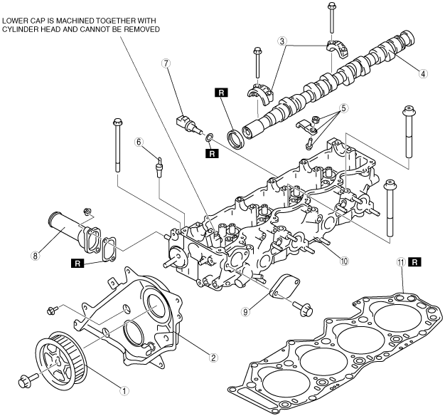
1. Disassemble in the order shown in the figure.
bwl1ge00000023
|
|
1
|
Camshaft pulley
|
|
2
|
Seal plate
|
|
3
|
Camshaft cap
|
|
4
|
Camshaft
(See Camshaft Disassembly Note.)
|
|
5
|
Rocker arm
|
|
6
|
Water temperature sender unit
|
|
7
|
ECT sensor
|
|
8
|
Water outlet pipe
|
|
9
|
Blind cover
|
|
10
|
Cylinder head
|
|
11
|
Cylinder head gasket
|
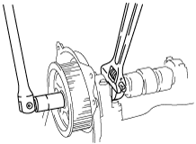
Camshaft Pulley Disassembly Note
1. Hold the camshaft by using a wrench on the cast hexagon.
bwl1ge00000024
|
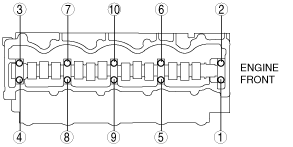
Camshaft Cap Disassembly Note
1. Loosen the camshaft cap bolts in three or four steps in the order shown in the figure.
bwl1ge00000025
|
Camshaft Disassembly Note
1. Before removing the camshaft, inspect the camshaft oil clearance. (See CAMSHAFT OIL CLEARANCE INSPECTION [WLT-1, WLT-2, WL-3].)
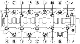
Cylinder Head Disassembly Note
1. Remove bolts A.
2. Loosen the cylinder head bolts in two or three steps in the order shown in the figure.
bwl1ge00000026
|