DTC 12 [WLT-2]
id010297235800
DTC 12 |
CONTROL LEVER POSITION SENSOR MALFUNCTION |
---|---|
DETECTION CONDITION
|
• Input voltage from control lever position sensor is below 0.1 V or above 4.75 V when continued for 1.0 S.
• When idle switch is on, input voltage from control lever position sensor is below 0.35 V or above 1.39 V.
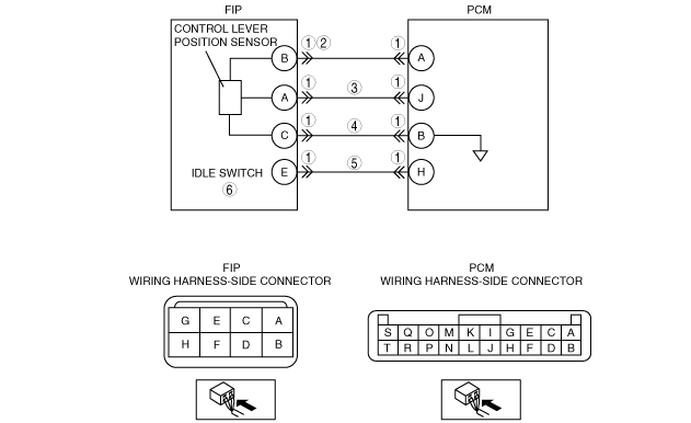
|
POSSIBLE CAUSE
|
• Control lever position sensor malfunction
• Idle switch malfunction
• Open circuit in wiring from control lever position sensor (FIP connector: 8 pin) terminal C to PCM terminal B
• Open or short circuit in wiring from control lever position sensor (FIP connector: 8 pin) terminal A to PCM terminal J
• Open or short circuit in wiring from control lever position sensor (FIP connector: 8 pin) terminal B to PCM terminal A
• Open or short circuit in wiring from idle switch (FIP connector: 8 pin) terminal E to PCM terminal H
|
![]() |
Diagnostic procedure
STEP |
INSPECTION |
ACTION |
|
---|---|---|---|
1
|
Does control lever position sensor connector or PCM connector have poor connection?
|
Yes
|
Repair or replace connector, then go to Step 7.
|
No
|
Go to the next step.
|
||
2
|
Disconnect control lever position sensor connector.
Turn engine switch on.
Is there 5 V at connector terminal B?
|
Yes
|
Go to the next step.
|
No
|
Inspection for open or short circuit in wiring harness.
(PCM terminal A and control lever position sensor terminal B)
|
||
3
|
Is there continuity between connector terminal A and PCM terminal J?
|
Yes
|
Go to the next step.
|
No
|
Repair or replace wiring harness, then go to Step 7.
|
||
4
|
Is there continuity between connector terminal C and PCM terminal B?
|
Yes
|
Replace control lever position sensor, then go to Step 7.
|
No
|
Repair or replace wiring harness, then go to Step 7.
|
||
5
|
Is there continuity between connector terminal E and PCM terminal H?
|
Yes
|
Go to the next step.
|
No
|
Repair or replace wiring harness, then go to Step 7.
|
||
6
|
Is idle switch normal?
|
Yes
|
Go to the next step.
|
No
|
Replace idle switch.
|
||
7
|
Clear DTC from memory.
Is same code No. present after performing “After Repair Procedure”?
|
Yes
|
Go to Step 1.
|
No
|
Intermittent poor connection in harnesses or connector.
Repair connectors and/or harnesses, then go to the next step.
|
||
8
|
Clear DTC from memory.
Is there any DTC present after performing “After Repair Procedure”?
|
Yes
|
Go to applicable DTC inspection.
(See DTC TABLE [WLT-2].)
|
No
|
Troubleshooting completed.
|