|
1
|
VERIFY FREEZE FRAME DATA HAS BEEN RECORDED
• Has FREEZE FRAME PID DATA been recorded?
|
Yes
|
Go to the next step.
|
|
No
|
Record the FREEZE FRAME PID DATA on the repair order, then go to the next step.
|
|
2
|
VERIFY RELATED REPAIR INFORMATION AVAILABILITY
• Verify related service repair Information availability.
• Is any related repair information available?
|
Yes
|
Perform repair or diagnosis according to the available service repair Information.
• If the vehicle is not repaired, go to the next step.
|
|
No
|
Go to the next step.
|
|
3
|
VERIFY CURRENT INPUT SIGNAL STATUS: IS CONCERN INTERMITTENT OR CONSTANT
• Connect the M-MDS to the DLC-2.
• Start engine.
• Access VSS PID.
• Read the VSS PID when the vehicle is driving.
• Is the VSS PID normal?
|
Yes
|
Intermittent concern exists.
Perform the “INTERMITTENT CONCERNS TROUBLESHOOTING“.
|
|
No
|
Go to the next step.
|
|
4
|
CHECK INPUT/OUTPUT CHECK MODE
• Turn the ignition switch to the ON position (Engine off).
• Is instrument cluster DTCs 10 or 12 detected?
|
Yes
|
DTC 10 and/or 12 displayed: Inspect instrument cluster.
|
|
No
|
Go to the next step.
|
|
5
|
INSPECT INSTRUMENT CLUSTER CONNECTOR FOR POOR CONNECTION
• Turn the ignition switch off.
• Disconnect instrument cluster connector.
• Inspect for poor connections (damaged/pulled-out terminals, corrosion, etc.).
• Are terminals normal?
|
Yes
|
Go to the next step.
|
|
No
|
Repair or replace terminals, then go to Step 10.
|
|
6
|
INSPECT VOLTAGE
• Turn the ignition switch to the ON position (Engine off).
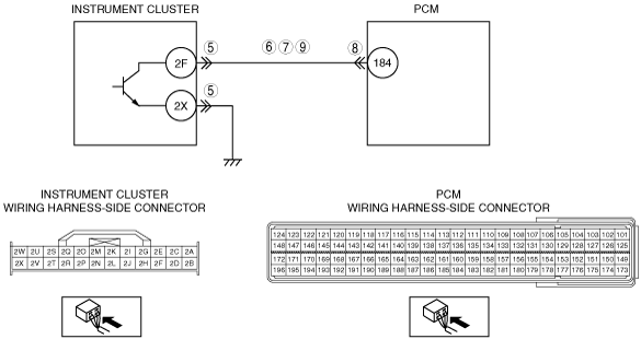
• Measure voltage at instrument cluster terminal 2F (wiring harness-side).
• Is there 5 V at instrument cluster terminal 2F (wiring harness-side)?
|
Yes
|
Replace instrument cluster, then go to Step 10.
|
|
No
|
Go to the next step.
|
|
7
|
INSPECT VSS CIRCUIT FOR SHORT TO GROUND
• Turn the ignition switch off.
• Inspect for continuity between instrument cluster terminal 2F (wiring harness-side) and body ground.
• Is there continuity?
|
Yes
|
Repair or replace harness, then go to Step 10.
|
|
No
|
Go to the next step.
|
|
8
|
INSPECT PCM CONNECTOR FOR POOR CONNECTION
• Turn the ignition switch off.
• Disconnect PCM connector.
• Inspect for poor connection (damaged/pulled-out terminals, corrosion, etc.).
• Are terminals normal?
|
Yes
|
Go to the next step.
|
|
No
|
Repair or replace pin or connector, then go to Step 10.
|
|
9
|
INSPECT VSS CIRCUIT FOR OPEN CIRCUIT
• Turn the ignition switch off.
• Turn the ignition switch to the ON position (Engine off).
• Inspect for continuity between instrument cluster terminal 2F (wiring harness-side) and PCM terminal 184 (wiring harness-side).
• Is there continuity?
|
Yes
|
Replace instrument cluster then go to the next step.
|
|
No
|
Repair or replace harness, then go to the next step.
|
|
10
|
VERIFY TROUBLESHOOTING OF DTC P0500 COMPLETED
• Turn the engine switch off.
• Make sure to reconnect all disconnected connectors.
• Turn the engine switch to the ON position (Engine off).
• Clear the DTC from the memory using the M-MDS.
• Start the engine.
• Retrieve DTCs using the M-MDS.
• Is the PENDING CODE for this DTC present?
|
Yes
|
Replace PCM, then go to the next step.
|
|
No
|
Go to the next step.
|
|
11
|
VERIFY AFTER REPAIR PROCEDURE
• Perform the “After Repair Procedure”.
• Are any DTC present?
|
Yes
|
Go to the applicable DTC inspection.
|
|
No
|
Troubleshooting completed.
|