|
1
|
VERIFY RELATED REPAIR INFORMATION AVAILABILITY
• Verify related service repair information availability.
• Is any related repair information available?
|
Yes
|
Perform repair or diagnosis according to the available repair information.
• If the vehicle is not repaired, go to the next step.
|
|
No
|
Go to the next step.
|
|
2
|
VERIFY CURRENT SIGNAL STATUS: IS CONCERN INTERMITTENT OR CONSTANT?
• Start the engine.
• Is the same DTC present?
|
Yes
|
Go to the next step.
|
|
No
|
Intermittent concern exists.
Perform the “INTERMITTENT CONCERN TROUBLESHOOTING”.
|
|
3
|
CHECK SPEEDOMETER
• Check the speedometer.
• Does the vehicle speedometer needle move?
|
Yes
|
Go to the next step.
|
|
No
|
Inspect the speedometer, then go to the next step.
|
|
4
|
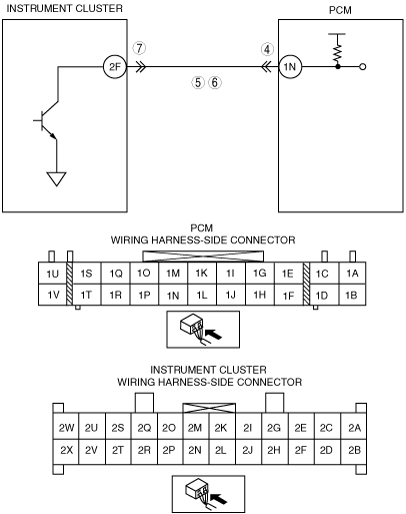
INSPECT POOR CONNECTION OF PCM CONNECTOR
• Disconnect the PCM connector.
• Check for poor connection at terminal 1N (damaged/pulled-out terminals, corrosion, etc.).
• Are there any concerns?
|
Yes
|
Repair or replace the terminal, then go to Step 8.
|
|
No
|
Go to the next step.
|
|
5
|
INSPECT INSTRUMENT CLUSTER CIRCUIT FOR OPEN CIRCUIT
• Check for continuity between PCM terminal 1N and instrument cluster 2F (wiring harness-side).
• Is there continuity?
|
Yes
|
Go to the next step.
|
|
No
|
Repair or replace wiring harness, then go to Step 8.
|
|
6
|
INSPECT INSTRUMENT CLUSTER CIRCUIT FOR SHORT TO GROUND
• Check for continuity between PCM terminal 1N (wiring harness-side) and body ground.
• Is there continuity?
|
Yes
|
Repair or replace wiring harness, then go to Step 8.
|
|
No
|
Go to the next step.
|
|
7
|
INSPECT INSTRUMENT CLUSTER CONNECTOR FOR POOR CONNECTION
• Disconnect instrument cluster connector.
• Check for poor connection at terminal 2F (damaged/pulled-out terminals, corrosion, etc.).
• Are there any concerns?
|
Yes
|
Repair or replace terminal, go to the next step.
|
|
No
|
Go to the next step.
|
|
8
|
VERIFY TROUBLESHOOTING OF DTC P0500 COMPLETED
• Make sure to reconnect all disconnected connectors.
• Turn the engine switch to the ON position (Engine off).
• Clear the DTCs from the memory using the M-MDS.
• Start the engine.
• Warm up the engine.
• Drive the vehicle under the following conditions for 10s or more.
-
― Engine speed: 4,000 rpm or above
― Gear: other than neutral.
― Vehicle speed: 3.76 km/h {2.33 mph} or above
• Is the same DTC present?
|
Yes
|
Replace the PCM, then go to the next step.
|
|
No
|
Go to the next step.
|
|
9
|
VERIFY AFTER REPAIR PROCEDURE
• Perform “After Repair Procedure”.
• Is there any DTC present?
|
Yes
|
Go to the applicable DTC inspection.
|
|
No
|
Troubleshooting completed.
|