|
1
|
VERIFY RELATED REPAIR INFORMATION AVAILABILITY
• Verify related service repair information availability.
• Is any related repair information available?
|
Yes
|
Perform repair or diagnosis according to the available repair information.
• If the vehicle is not repaired, go to the next step.
|
|
No
|
Go to the next step.
|
|
2
|
VERIFY CURRENT SIGNAL STATUS: IS CONCERN INTERMITTENT OR CONSTANT?
• Start the engine.
• Is the same DTC present?
|
Yes
|
Go to the next step.
|
|
No
|
Intermittent concern exists.
Perform the “INTERMITTENT CONCERN TROUBLESHOOTING”.
|
|
3
|
VERIFY CURRENT INPUT SIGNAL STATUS‐HIGH OR LOW INPUT
• Start the engine.
• Access the IAT2 PID using the M-MDS.
• Is the IAT2 PID within 0.13—4.90 V?
|
Yes
|
Go to Step 16.
|
|
No
|
• If the IAT2 PID is below 0.13 V, go to the next step.
• If the IAT2 PID is above 4.90 V, go to Step 9.
|
|
4
|
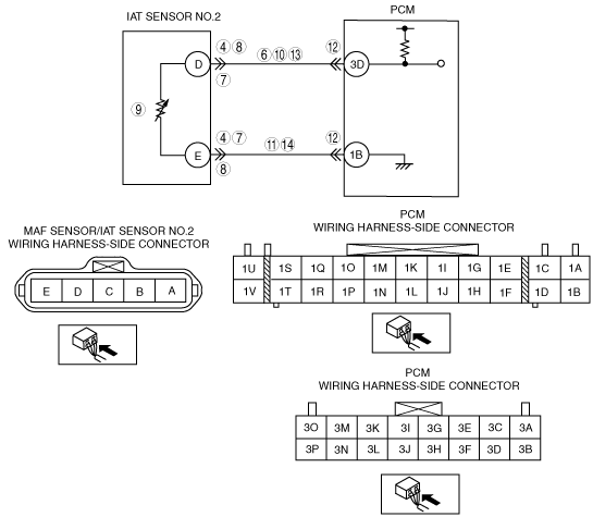
INSPECT IAT SENSOR NO.2 TERMINAL
• Turn the engine switch to the off position.
• Disconnect the MAF sensor/IAT sensor No.2 connector.
• Check for a bent terminal of MAF sensor/IAT sensor No.2 terminals D and E (part-side).
• Is there a malfunction?
|
Yes
|
Repair or replace the terminal, then go to Step 16.
|
|
No
|
Go to the next step.
|
|
5
|
CLASSIFY IF IAT SENSOR NO.2 MALFUNCTION OR WIRING HARNESS MALFUNCTION
• Turn the engine switch to the ON position (Engine off).
• Access the IAT2 PID using the M-MDS.
• Is the IAT2 PID below 0.13 V?
|
Yes
|
Go to the next step.
|
|
No
|
Go to Step 10.
|
|
6
|
INSPECT IAT SENSOR NO.2 SIGNAL CIRCUIT FOR SHORT TO GROUND
• Turn the engine switch to the off position.
• Disconnect the PCM connector.
• Check for continuity between the MAF sensor/IAT sensor No.2 terminal D (wiring harness-side) and body ground.
• Is there continuity?
|
Yes
|
Repair or replace the shorted wiring harness, then go to Step 16.
|
|
No
|
Go to the next step.
|
|
7
|
INSPECT IAT SENSOR NO.2 CIRCUITS FOR SHORT
• Check for continuity between the MAF sensor/IAT sensor No.2 terminals D and E (wiring harness-side).
• Is there continuity?
|
Yes
|
Repair or replace the shorted wiring harness, then go to Step 16.
|
|
No
|
Go to Step 16.
|
|
8
|
INSPECT MAF SENSOR/IAT SENSOR NO.2 CONNECTOR FOR POOR CONNECTION
• Turn the engine switch to the off position.
• Disconnect the MAF sensor/IAT sensor No.2 connector.
• Check for poor connection (damaged, pulled-out pins, corrosion, etc.).
• Is there a malfunction?
|
Yes
|
Repair or replace the terminal, then go to Step 16.
|
|
No
|
Go to the next step.
|
|
9
|
INSPECT IAT SENSOR NO.2
• Inspect the IAT sensor No.2.
• Is it normal?
|
Yes
|
Go to the next step.
|
|
No
|
Replace the MAF sensor/IAT sensor No.2, then go to Step 16.
|
|
10
|
INSPECT IAT SENSOR NO.2 SIGNAL CIRCUIT FOR SHORT TO POWER
• Turn the engine switch to the ON position (Engine off).
• Measure the voltage between the MAF sensor/IAT sensor No.2 terminal D (wiring harness-side) and body ground.
• Is the voltage B+?
|
Yes
|
Repair or replace the shorted wiring harness, then go to Step 16.
|
|
No
|
Go to the next step.
|
|
11
|
INSPECT IAT SENSOR NO.2 GROUND CIRCUIT FOR SHORT TO POWER
• Measure the voltage between IAT sensor No.2 terminal E (wiring harness-side) and body ground.
• Is the voltage B+?
|
Yes
|
Repair or replace the shorted wiring harness, then go to Step 16.
|
|
No
|
Go to the next step.
|
|
12
|
INSPECT PCM CONNECTOR FOR POOR CONNECTION
• Turn the engine switch to the off position.
• Disconnect the PCM connector.
• Inspect for poor connection (such as damaged/pulled-out pins, corrosion).
• Is there a malfunction?
|
Yes
|
Repair or replace the terminal, then go to Step 16.
|
|
No
|
Go to the next step.
|
|
13
|
INSPECT IAT SENSOR NO.2 SIGNAL CIRCUIT FOR OPEN CIRCUIT
• Check for continuity between the MAF sensor/IAT sensor No.2 terminal D (wiring harness-side) and PCM terminal 3D.
• Is there continuity?
|
Yes
|
Go to the next step.
|
|
No
|
Repair or replace open wiring harness, then go to Step 16.
|
|
14
|
INSPECT IAT SENSOR NO.2 GROUND CIRCUIT FOR OPEN CIRCUIT
• Check for continuity between the MAF sensor/IAT sensor No.2 terminal E (wiring harness-side) and PCM terminal 1B (wiring harness‐side).
• Is there continuity?
|
Yes
|
Go to the next step.
|
|
No
|
Repair or replace open wiring harness, then go to the next step.
|
|
15
|
VERIFY TROUBLESHOOTING OF DTC P1110 COMPLETED
• Make sure to reconnect all disconnected connectors.
• Clear the DTC from the PCM memory.
• Start the engine.
• Is the same DTC present?
|
Yes
|
Replace the PCM, then go to the next step.
|
|
No
|
Go to the next step.
|
|
16
|
VERIFY AFTER REPAIR PROCEDURE
• Perform “AFTER REPAIR PROCEDURE”.
• Is there any DTC present?
|
Yes
|
Go to the applicable DTC inspection.
|
|
No
|
Troubleshooting completed.
|