|
1
|
VERIFY RELATED REPAIR INFORMATION AVAILABILITY
• Verify related service repair information availability.
• Is any related repair information available?
|
Yes
|
Perform repair or diagnosis according to the available repair information.
• If the vehicle is not repaired, go to the next step.
|
|
No
|
Go to the next step.
|
|
2
|
VERIFY CURRENT SIGNAL STATUS: IS CONCERN INTERMITTENT OR CONSTANT?
• Start the engine.
• Is the same DTC present?
|
Yes
|
Go to the next step.
|
|
No
|
Intermittent concern exists.
Perform the “INTERMITTENT CONCERN TROUBLESHOOTING”.
|
|
3
|
INSPECT INJECTION PUMP EPROM CONNECTOR FOR POOR CONNECTION
• Turn the engine switch to the off position.
• Disconnect the injection pump EPROM connector.
• Check for poor connection (damaged, pulled-out pins, corrosion, etc.).
• Is there a malfunction?
|
Yes
|
Repair or replace the terminal, then go to Step 9.
|
|
No
|
Go to the next step.
|
|
4
|
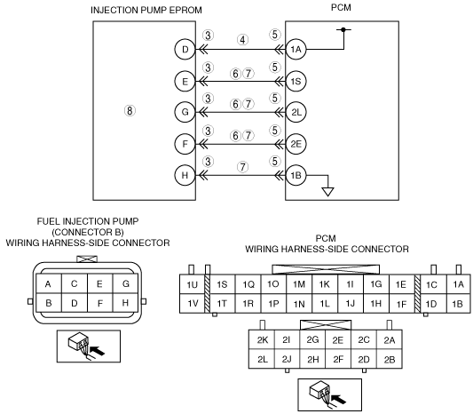
INSPECT INJECTION PUMP EPROM POWER CIRCUIT FOR OPEN CIRCUIT
• Measure the voltage between fuel injection pump connector B terminal D (wiring harness-side) and body ground.
• Is the voltage approx. 5V?
|
Yes
|
Go to the next step.
|
|
No
|
Repair or replace open wiring harness, then go to Step 9.
|
|
5
|
INSPECT PCM CONNECTOR FOR POOR CONNECTION
• Turn the engine switch to the off position.
• Disconnect the PCM connector.
• Check for poor connection (damaged, pulled-out pins, corrosion, etc.).
• Is there a malfunction?
|
Yes
|
Repair or replace the terminal, then go to Step 9.
|
|
No
|
Go to the next step.
|
|
6
|
INSPECT INJECTION PUMP EPROM CIRCUIT FOR SHORT TO GROUND
• Inspect the following terminals for continuity:
-
― Between fuel injection pump connector B terminal F and body ground
― Between fuel injection pump connector B terminal G and body ground
― Between fuel injection pump connector B terminal E and body ground
• Is there continuity?
|
Yes
|
Repair or replace wiring harness, then go to Step 9.
|
|
No
|
Go to the next step.
|
|
7
|
INSPECT INJECTION PUMP EPROM CIRCUIT FOR OPEN CIRCUIT
• Inspect the following terminals for continuity:
-
― Between fuel injection pump connector B terminal F and PCM terminal 2E
― Between fuel injection pump connector B terminal G and PCM terminal 2L
― Between fuel injection pump connector B terminal E and PCM terminal 1S
― Between fuel injection pump connector B terminal H and PCM terminal 1B
• Is there continuity?
|
Yes
|
Go to the next step.
|
|
No
|
Repair or replace open wiring harness, then go to Step 9.
|
|
8
|
INSPECT INJECTION PUMP EPROM
• Perform injection pump EPROM inspection.
• Is the injection pump EPROM normal?
|
Yes
|
The fuel injection pump may have a malfunction. Consult your distributor for the inspection of the fuel injection pump.
Go to the next step.
|
|
No
|
Consult your distributor for the replacement of the injection pump EPROM.
Go to the next step.
|
|
9
|
VERIFY TROUBLESHOOTING OF DTC P1649 COMPLETED
• Turn engine switch to OFF and ON (Engine off).
• Clear the DTCs from memory using M-MDS.
• Start the engine.
• Is the same DTC present?
|
Yes
|
Replace PCM, then go to the next step.
|
|
No
|
Go to the next step.
|
|
10
|
VERIFY AFTER REPAIR PROCEDURE
• Perform “AFTER REPAIR PROCEDURE”.
• Is there any DTC present?
|
Yes
|
Go to the applicable DTC inspection.
|
|
No
|
Troubleshooting completed.
|