 |
absggw00000058
CYLINDER HEAD GASKET REPLACEMENT [G6]
id011095800700
1. Disconnect the negative battery cable.
2. Drain the engine coolant. (See ENGINE COOLANT REPLACEMENT [G6].)
3. Remove the drive belt. (See DRIVE BELT ADJUSTMENT [G6].)
4. Remove the cooling fan.
5. Remove the front pipe.
6. Remove the air intake pipe and resonance chamber.
7. Disconnect the accelerator cable and bracket.
8. Disconnect the vacuum hoses, water hoses, and engine harness connectors.
9. Disconnect the fuel hoses. (See BEFORE REPAIR PROCEDURE [G6].) (See AFTER REPAIR PROCEDURE [G6].)
10. Remove the intake manifold bracket.
11. Remove the distributor. (See DISTRIBUTOR REMOVAL/INSTALLATION [G6].)
12. Remove the high-tension lead. (See HIGH-TENSION LEAD REMOVAL/INSTALLATION [G6].)
13. Remove the spark plug.
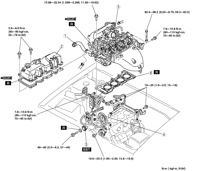
14. Remove in the order indicated in the table.
15. Install in the reverse order of removal.
16. Inspect for fuel leakage.
17. Inspect the compression. (See COMPRESSION INSPECTION [G6].)
18. Start the engine and
absggw00000058
|
|
1
|
Upper radiator hose
|
|
2
|
Cylinder head cover
|
|
3
|
Distributor drive gear
|
|
4
|
Camshaft sprocket
|
|
5
|
Cylinder head
(See Cylinder Head Removal Note.)
|
|
6
|
Cylinder head gasket
|
Distributor Drive Gear Removal Note
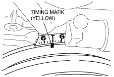
1. Turn the crankshaft clockwise so that the No.1 piston is at TDC of the compression stroke.
absggw00000059
|
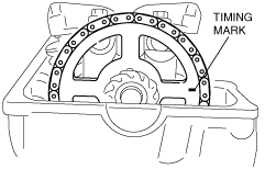
2. Verify that the camshaft sprocket mark is aligned with the horizontal surface on the cylinder head.
absggw00000072
|
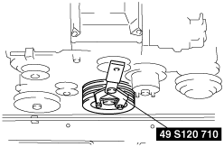
3. Remove the seal cover.
4. Hold the crankshaft using the SST.
absggw00000061
|
5. Remove the lock bolt.
Camshaft Sprocket Removal Note
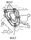
1. Remove the service cover on the chain cover.
absggw00000062
|
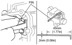
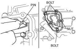
2. Push the chain adjuster sleeve in (toward the left) and insert a pin as shown into the lever hole to hold the sleeve.
absggw00000063
|
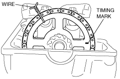
3. Secure the camshaft sprocket and the chain with a wire as shown.
absggw00000064
|
4. Remove the camshaft sprocket off the camshaft dowel pin.
Cylinder Head Removal Note
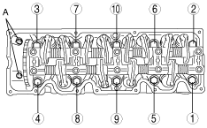
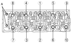
1. Remove the bolts A.
2. Loosen the cylinder head bolts a few turns in the order shown.
absggw00000065
|
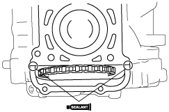
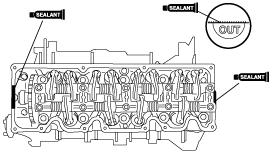
Cylinder Head Gasket Installation Note
1. Apply silicone sealant to the areas shown.
absggw00000066
|
Cylinder Head Installation Note
1. Tighten the cylinder head bolts a few turns in the order shown.
2. Tighten the bolts A.
absggw00000073
|
Camshaft Sprocket Installation Note
1. Install the camshaft sprocket onto the camshaft dowel pin.
2. Remove the wire securing the camshaft sprocket and chain.
absggw00000064
|
3. Remove the retaining pin from the chain adjuster.
4. Install the service cover with a new gasket.
absggw00000068
|
Distributor Drive Gear Installation Note
1. Install the distributor drive gear with a new washer and lock bolt.
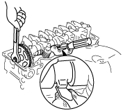
2. Hold the camshaft with a screwdriver as shown.
absggw00000069
|
3. Tighten the lock bolt.
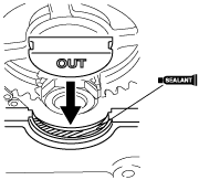
4. Apply silicone sealant to the areas shown.
absggw00000070
|
5. Install the new seal cover.
Cylinder Head Cover Installation Note
1. Verify that the grooves on the cylinder head cover are free of oil, water, and other foreign material.
2. Coat a new gasket with silicone sealant, and install it onto the cylinder head cover.
3. Apply silicone sealant to the cylinder head as shown.
absggw00000071
|
4. Install the cylinder head cover.