 |
absggw00001590
VALVE CLEARANCE INSPECTION [WL-3]
id0110b5803400
1. Remove the following parts to turn the crankshaft.
2. Remove the EGR pipe. (See EGR SYSTEM REMOVAL/INSTALLATION [WL-3].)
3. Remove the cylinder head cover.
4. Turn the crankshaft and align the timing mark so that the piston of the No. 1 or No. 4 cylinders is at TDC of the compression.
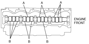
5. Measure the valve clearances A with the No.1 cylinder at TDC of compression, and those of B with the No.4 cylinder at TDC of compression.
absggw00001590
|
absggw00001591
|
6. Turn the crankshaft one full turn and measure the remaining valve clearances.
7. Install the cylinder head cover. (See CYLINDER HEAD GASKET REPLACEMENT [WL-3].)
8. Install the EGR pipe. (See EGR SYSTEM REMOVAL/INSTALLATION [WL-3].)