 |
absggw00002141
CYLINDER HEAD GASKET REPLACEMENT [WL-C, WE-C]
id0110b6800700
1. Remove the engine cover.
2. Disconnect the negative battery cable.
3. Drain the engine coolant. (See COOLING SYSTEM SERVICE WARNINGS [WL-C, WE-C].)
4. Remove the intake manifold, air intake pipe and breather chamber. (See INTAKE-AIR SYSTEM REMOVAL/INSTALLATION [WL-C, WE-C].)
5. Remove the fuel injector. (See FUEL INJECTOR REMOVAL/INSTALLATION [WL-C, WE-C].)
6. Remove the turbocharger. (See EXHAUST SYSTEM REMOVAL/INSTALLATION [WL-C, WE-C].)
7. Remove the timing belt. (See TIMING BELT REMOVAL/INSTALLATION [WL-C, WE-C].)
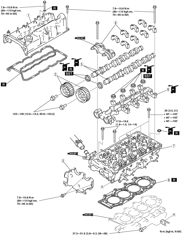
8. Remove in the order indicated in the table.
9. Install in the reverse order of removal.
10. Adjust the drive belt deflection. (See DRIVE BELT ADJUSTMENT [WL-C, WE-C].)
11. Bleed air in the fuel line. (See AFTER REPAIR PROCEDURE [WL-C, WE-C].)
12. Start the engine and
13. Inspect the compression.
absggw00002141
|
|
1
|
Cylinder head cover
|
|
2
|
Camshaft pulley
(See Camshaft Pulley Removal Note.)
(See Seal Plate Installation Note.)
|
|
3
|
Seal plate
(See Seal Plate Installation Note.)
|
|
4
|
Camshaft cap upper
|
|
5
|
Camshaft
|
|
6
|
Camshaft cap lower
|
|
7
|
Cylinder head
(See Cylinder Head Removal Note.)
|
|
8
|
Cylinder head gasket
|
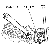
Camshaft Pulley Removal Note
1. Hold the camshaft by using a wrench on the cast hexagon.
absggw00000505
|
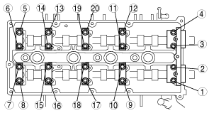
Camshaft Cap Upper Removal Note
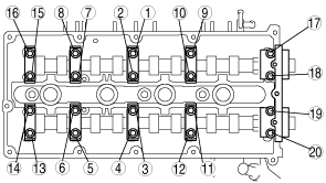
1. Loosen the camshaft cap bolts in three or four steps in the order shown.
absggw00000506
|
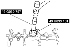
Camshaft Cap Lower Removal Note
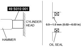
1. Tap the oil seal in evenly using the SST and a hammer.
absggw00000525
|
Cylinder Head Removal Note
1. Remove bolts A.
2. Loosen the cylinder head bolts in two or three steps in the order shown.
absggw00000507
|
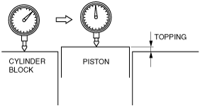
Cylinder Head Gasket Installation Note
1. Measure the piston topping of all the cylinders.
absggw00000508
|
2. Choose the gasket according to each measured piston topping.
absggw00000509
|
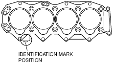
Cylinder head gasket select table
|
Piston topping (mm {in}) |
Cylinder head gasket identification mark |
|---|---|
|
0.080—0.190 {0.004—0.007}
|
 |
|
0.135—0.255 {0.006—0.010}
|
 |
|
0.200—0.310 {0.008—0.012}
|
 |
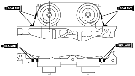
3. Apply silicone sealant to the cylinder block as shown.
absggw00000513
|
Cylinder Head Installation Note
1. Measure the length of each bolt. Replace the bolt if necessary.
absggw00000514
|
2. Apply clean engine oil to the threads and the seat face of each bolt and install them.
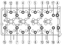
3. Tighten the bolts in two or three steps in the order shown in the figure.
absggw00000515
|
4. Retighten the bolts in the order shown in the figure until all the bolts are tightened to 29 N·m {3.0 kgf·m, 2.1 ft·lbf}.
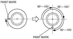
5. Put a paint mark on each bolt head.
absggw00000516
|
6. Using the marks as a reference, tighten the bolts by turning each 90°—105°in the sequence shown.
7. Further tighten each bolt by turning another 90°—105°.
8. Further tighten each bolt by turning another 90°—105°.
9. Apply adhesive to the thread of bolt A.
10. Tighten bolts A.
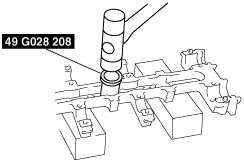
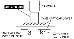
Camshaft Cap Lower Installation Note
1. Apply engine oil along the perimeter of the new oil seal.
2. Push the oil seal slightly in by hand.
3. Tap the oil seal in evenly using the SST and a hammer.
absggw00000530
|
4. To ensure that the oil seal is installed correctly, measure the distance between the end of the camshaft cap lower and the face of the camshaft cap lower oil seal.
absggw00000616
|
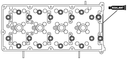
5. Apply silicone sealant to the cylinder head as shown in the figure.
absggw00000517
|
Camshaft Cap Upper Installation Note
1. Apply adhesive to the front camshaft cap mounting surfaces as shown.
absggw00000518
|
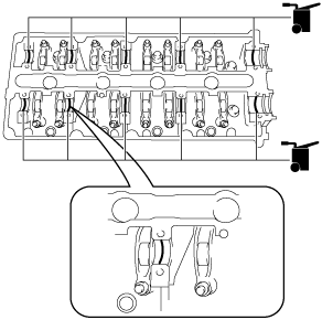
2. Apply the gear oil (SAE No. 90 or equivalent) to each journal of the camshaft cap lower as shown in the figure.
absggw00002142
|
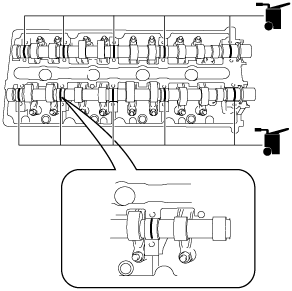
3. Apply the gear oil (SAE No. 90 or equivalent) to each journal of the camshaft as shown in the figure.
absggw00002144
|
4. Tighten the camshaft cap bolts gradually in three or four steps in the order shown.
absggw00000519
|
5. Apply soapy water along the perimeter of the new oil seal.
6. Push the oil seal slightly in by hand.
7. Tap the oil seal lightly into the cylinder head using the SST and a hammer.
absggw00000520
|
8. To ensure that the oil seal is installed correctly, measure the distance between the end of the cylinder head and the face of the oil seal.
Seal Plate Installation Note
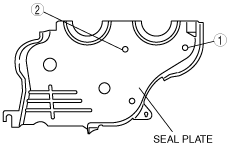
1. Tighten the seal plate bolts in the order indicated in the figure.
absggw00000521
|
Camshaft Pulley Installation Note
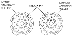
1. Install the camshaft pulleys, positioning the knock pins as shown.
absggw00000522
|
2. Hold the camshaft using a wrench on the cast hexagon.
absggw00000505
|
Cylinder Head Cover Installation Note
1. Apply silicone sealant to the cylinder head as shown.
absggw00000523
|
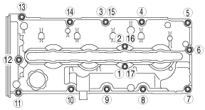
2. Tighten the cylinder head cover bolts in the order shown.
absggw00000524
|