VALVE CLEARANCE ADJUSTMENT [WL-C, WE-C]
id0110b6803300
-
Caution
-
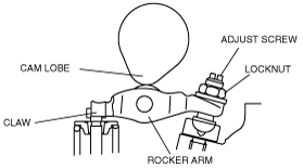
• Loosening the locknut and the adjust screw while the cam lobe is not pressing down the rocker arm will damage the claw of the rocker arm. When loosening the locknut and the adjust screw, rotate the crankshaft clockwise and be sure that the cam lobe presses down the rocker arm firmly as shown in the figure.
1. Remove the engine cover.
2. Remove the following parts to turn the crankshaft.
-
3. Water pump pulley.
3. Remove the fuel injector. (See FUEL INJECTOR REMOVAL/INSTALLATION [WL-C, WE-C].)
4. Remove the cylinder head cover.
5. Turn the crankshaft and align the timing mark so that the piston of the No. 1 or No. 4 cylinders is at TDC of compression.
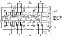
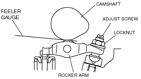
6. Adjust the valve clearances A with the No.1 cylinder at TDC of compression, and those of B with the No.4 cylinder at TDC of compression.
-
Valve clearance [Engine cold]
-
IN: 0.10—0.16 mm {0.0040—0.0062 in}
EX: 0.17—0.23 mm {0.0067—0.0090 in}
-
Tightening torque (lock nut)
-
20—24 N·m {2.1—2.4 kgf·m, 15—17 ft·lbf}
7. Turn the crankshaft one full turn and measure the remaining valve clearances. Adjust if necessary.
8. Install the cylinder head cover. (See CYLINDER HEAD GASKET REPLACEMENT [WL-C, WE-C].)
9. Install the fuel injector. (See FUEL INJECTOR REMOVAL/INSTALLATION [WL-C, WE-C].)
10. Install the water pump pulley, cooling fan and drive belt.
11. Adjust the drive belt deflection. (See DRIVE BELT ADJUSTMENT [WL-C, WE-C].)
12. Install the engine cover.