 |
absggw00002025
ACCELERATOR PEDAL ADJUSTMENT [WL-3]
id0113a9807400
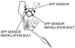
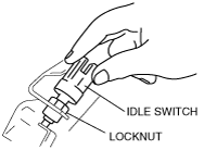
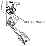
1. Temporarily install the APP sensor and the idle switch to the pedal assembly and verify that the APP sensor installation bolts and idle switch locknut are lightly tightened.
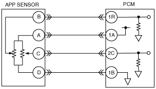
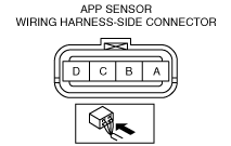
2. Connect the APP sensor and the idle switch connector.
3. Turn the engine switch to the ON position.
4. Verify that the voltage between APP sensor terminals A and D is between 4.9 to 5.1 V (target value 5.0 V).
absggw00002025
|
absggw00002026
|
5. Set the M-MDS and monitor TP and TP2 V PIDs. (See ON-BOARD DIAGNOSTIC TEST [WL-3].)
6. Adjust the APP sensor installation position so that the TP and TP2 V PIDs value is between 0.5 to 0.7 V (target value 0.6 V) with the accelerator pedal fully released, then tighten the APP sensor installation bolts
absggw00002027
|
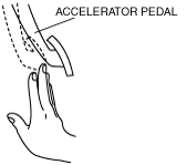
7. While slowly depressing the accelerator pedal by hand, adjust the idle switch installation position so that the idle switch turns from ON to OFF (output voltage change) with the TP and TP2 V value is between 1.0 to 1.2 V (target value 1.1 V), then tighten the idle switch locknut.
absggw00002028
|
absggw00002029
|
8. Verify that the idle switch turns from OFF to ON (output voltage change) when the accelerator pedal is full released.
9. While depressing the accelerator pedal again, verify that the idle switch turns from ON to OFF (output voltage change) with the TP and TP2 V PIDs value is between 1.0 to 1.2 V (target value 1.1 V).
10. While fully depressing the accelerator pedal until it contacts the accelerator pedal bracket, verify that APP sensor the TP and TP2 V value is between 3.4 to 3.8 V (target value 3.6 V).
absggw00002030
|