 |
dbg140awb701
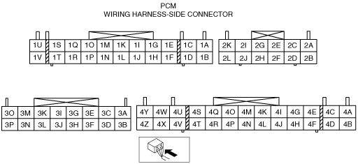
PCM INSPECTION [WL-3]
id0140b5802500
Without Using the M-MDS
dbg140awb701
|
Terminal voltage table (Reference)
|
Terminal |
Signal |
Connected to |
Test condition |
Voltage (V) |
Inspection item |
|
|---|---|---|---|---|---|---|
|
1A
|
Constant voltage
(Vref)
|
Injection pump EPROM, EGR valve position sensor, Boost sensor, APP sensor
|
Engine switch ON
|
Approx. 5
|
• Inspect related wiring harness
• Injection pump EPROM
• EGR valve position sensor
• Boost sensor
• APP sensor
|
|
|
1B
|
Ground
|
Body ground
|
Under any condition
|
Below 1.0
|
• Inspect related wiring harness
|
|
|
1C
|
Power supply
|
Power supply
|
Under any condition
|
B+
|
• Inspect related wiring harness
|
|
|
1D
|
Clutch
|
CPP switch
|
Clutch pedal depressed
|
Below 1.0
|
• Inspect related wiring harness
• CPP switch
|
|
|
Clutch pedal released
|
B+
|
|||||
|
1E
|
—
|
—
|
—
|
—
|
—
|
|
|
1F
|
EGR position
|
EGR valve
|
Engine switch ON
|
Below 1.0
|
• Inspect related wiring harness
• EGR valve
|
|
|
EGR valve operating
|
Approx. 3
|
|||||
|
1G
|
Ground
|
Timer position sensor
|
Under any condition
|
Below 1.0
|
• Inspect related wiring harness
|
|
|
1H
|
CKP
|
CKP sensor
|
Inspection using the wave Profile.
|
• Inspect related wiring harness
• CKP sensor
|
||
|
1I
|
Timer position
|
Timer position sensor
|
Engine switch ON
|
Approx. 2.5
|
|
|
|
1J
|
IAT
|
IAT sensor No.1
|
Engine switch ON
|
IAT 20 °C
{68 °F}
|
2.3—2.5
|
• Inspect related wiring harness
• IAT sensor No.1
|
|
IAT 30 °C
{86 °F}
|
1.8—2.0
|
|||||
|
1K
|
Constant voltage
|
Timer position sensor
|
Engine switch ON
|
Approx. 5
|
• Inspect related wiring harness
• Timer position sensor
|
|
|
1L
|
Fuel temp
|
Fuel temperature sensor
|
Engine switch ON
|
Fuel temperature
20 °C {68 °F}
|
2.4—2.6
|
• Inspect related wiring harness
• Fuel temperature sensor
|
|
Fuel temperature
70 °C {158 °F}
|
0.7—0.9
|
|||||
|
1M
|
Ground
|
Control sleeve position sensor
|
Under any condition
|
Below 1.0
|
• Inspect related wiring harness
• Control sleeve position sensor
|
|
|
1N
|
Vehicle speed
|
VSS
|
Inspection using the wave Profile.
|
• Inspect related wiring harness
• VSS
|
||
|
1O
|
Control sleeve position
|
Control sleeve position sensor
|
Engine switch ON
|
Approx. 2.5
|
• Inspect related wiring harness
• Control sleeve position sensor
|
|
|
1P
|
MAP
|
Boost sensor
|
Engine switch ON
|
Approx. 2.6
|
• Inspect related wiring harness
• Boost sensor
|
|
|
1Q
|
Constant voltage
|
Control sleeve position sensor
|
Engine switch ON
|
Approx. 2.5
|
• Inspect related wiring harness
• Control sleeve position sensor
|
|
|
1R
|
APP
|
APP sensor
|
Accelerator pedal released
|
0.5—0.7
|
• Inspect related wiring harness
• APP sensor
|
|
|
Accelerator pedal depressed
|
3.4—3.8
|
|||||
|
1S
|
Injection pump
|
Injection pump EPROM
|
Engine switch ON
|
Approx. 8.5
|
• Inspect related wiring harness
• Injection pump EPROM
|
|
|
Idle
|
Approx. 9.5
|
|||||
|
1T
|
ECT
|
ECT sensor
|
Engine switch ON
|
ECT 30 °C
{86 °F}
|
Approx. 2.6
|
• Inspect related wiring harness
• ECT sensor
|
|
ECT 50 °C
{122 °F}
|
Approx. 1.7
|
|||||
|
ECT 60 °C
{140 °F}
|
Approx. 1.4
|
|||||
|
ECT 80 °C
{176 °F}
|
Approx. 0.8
|
|||||
|
1U
|
Starter
|
Engine switch, Starter relay
|
Engine switch ON (START) position
|
B+
|
• Inspect related wiring harness
|
|
|
Except for engine switch ON (START) position
|
Below 1.0
|
|||||
|
1V
|
IG1
|
Engine switch
|
Engine switch ON and Start position
|
B+
|
• Inspect related wiring harness
|
|
|
Engine switch is other position
|
Below 1.0
|
|||||
|
2A
|
Diagnostic test mode
|
Data link connector (DLC) (Terminal TEN)
|
Engine switch ON
|
Open terminal TEN
|
B+
|
• Inspect related wiring harness
|
|
Short terminal TEN
|
Below 1.0
|
|||||
|
2B
|
Serial communication
|
Data link connector (DLC) (Terminal KLN)
|
Because this terminal is for serial communication, good/no good judgement by terminal voltage is not possible. Carry out inspection according to diagnostic trouble codes.
|
—
|
||
|
2C
|
APP
|
APP sensor
|
Accelerator pedal released
|
0.5—0.7
|
• Inspect related wiring harness
• APP sensor
|
|
|
Accelerator pedal depressed
|
3.4—3.8
|
|||||
|
2D
|
Injection pump
(Np–)
|
Injection pump
|
Inspection using the wave Profile.
|
• Inspect related wiring harness
• Injection pump
|
||
|
2E
|
Injection pump
|
Injection pump EPROM
|
Engine switch ON
|
Below 1.0
|
• Inspect related wiring harness
|
|
|
Idle
|
Approx. 4
|
|||||
|
2F
|
—
|
—
|
—
|
—
|
—
|
|
|
2G
|
—
|
—
|
—
|
—
|
—
|
|
|
2H
|
—
|
—
|
—
|
—
|
—
|
|
|
2I
|
—
|
—
|
—
|
—
|
—
|
|
|
2J
|
Tachometer
|
Tachometer
|
Engine switch ON
|
Below 1.0
|
• Inspect related wiring harness
• Tachometer
|
|
|
Idle
|
B+
|
|||||
|
2K
|
Injection pump
(Np+)
|
Injection pump
|
Inspection using the wave Profile.
|
• Inspect related wiring harness
• Injection pump
|
||
|
2L
|
Injection pump
|
Injection pump EPROM
|
Engine switch ON
|
Below 1.0
|
• Inspect related wiring harness
|
|
|
Idle
|
Approx. 4
|
|||||
|
3A
|
Main relay control
|
Main relay
|
Engine switch ON
|
Below 1.0
|
• Inspect related wiring harness
• Main relay
|
|
|
Engine switch OFF
|
B+
|
|||||
|
3B
|
—
|
—
|
—
|
—
|
—
|
|
|
3C
|
Cooling fan
|
Cooling fan switch
|
Engine switch ON
|
A/C operating
|
B+
|
• Inspect related wiring harness
|
|
A/C not operating
|
Approx. 0.87
|
|||||
|
3D
|
IAT
|
MAF sensor/IAT sensor No.2
|
Engine switch ON
|
IAT 20 °C
{68 °F}
|
2.3—2.5
|
• Inspect related wiring harness
• MAF sensor/IAT sensor No.2
|
|
IAT 30 °C
{86 °F}
|
1.8—2.0
|
|||||
|
3E
|
—
|
—
|
—
|
—
|
—
|
|
|
3F
|
—
|
—
|
—
|
—
|
—
|
|
|
3G
|
—
|
—
|
—
|
—
|
—
|
|
|
3H
|
—
|
—
|
—
|
—
|
—
|
|
|
3I
|
—
|
—
|
—
|
—
|
—
|
|
|
3J
|
—
|
—
|
—
|
—
|
—
|
|
|
3K
|
—
|
—
|
—
|
—
|
—
|
|
|
3L
|
—
|
—
|
—
|
—
|
—
|
|
|
3M
|
—
|
—
|
—
|
—
|
—
|
|
|
3N
|
—
|
—
|
—
|
—
|
—
|
|
|
3O
|
Idle switch
|
Idle switch
|
Accelerator pedal released
|
Below 1.0
|
• Inspect related wiring harness
• Idle switch
|
|
|
Accelerator pedal depressed
|
B+
|
|||||
|
3P
|
—
|
—
|
—
|
—
|
—
|
|
|
4A
|
Ground
|
Body ground
|
Under any condition
|
Below 1.0
|
• Inspect related wiring harness
|
|
|
4B
|
Ground
|
Body ground
|
Under any condition
|
Below 1.0
|
• Inspect related wiring harness
|
|
|
4C
|
B+
|
Main relay
|
Main relay ON
|
B+
|
• Inspect related wiring harness
• Main relay
|
|
|
Main relay OFF
|
Below 1.0
|
|||||
|
4D
|
B+
|
Main relay
|
Main relay ON
|
B+
|
• Inspect related wiring harness
• Main relay
|
|
|
Main relay OFF
|
Below 1.0
|
|||||
|
4E
|
MAF
|
MAF sensor/IAT sensor No.2
|
Engine switch ON
|
Below 1.0
|
• Inspect related wiring harness
• MAF sensor/IAT sensor No.2
|
|
|
Idle
|
1.6—2.0
|
|||||
|
4F
|
—
|
—
|
—
|
—
|
—
|
|
|
4G
|
—
|
—
|
—
|
—
|
—
|
|
|
4H
|
—
|
—
|
—
|
—
|
—
|
|
|
4I
|
EGR control solenoid valve
|
EGR control solenoid valve
|
Engine speed is 3,000 rpm
|
B+
|
• Inspect related wiring harness
• EGR control solenoid valve
|
|
|
Idle
|
Below 1.0
|
|||||
|
4J
|
—
|
—
|
—
|
—
|
—
|
|
|
4K
|
DTC output
|
Data link connector (DLC) (Terminal FEN)
|
No DTC output
|
Below 1.0
|
• Inspect related wiring harness
|
|
|
DTC output
|
0—B+
|
|||||
|
4L
|
A/C
|
A/C relay
|
A/C operating
|
Below 1.0
|
• Inspect related wiring harness
• A/C relay
|
|
|
A/C not operating
|
B+
|
|||||
|
4M
|
—
|
—
|
—
|
—
|
—
|
|
|
4N
|
—
|
—
|
—
|
—
|
—
|
|
|
4O
|
—
|
—
|
—
|
—
|
—
|
|
|
4P
|
—
|
—
|
—
|
—
|
—
|
|
|
4Q
|
EGRA
|
EGR solenoid valve
(Vent)
|
Engine switch ON
|
B+
|
• Inspect related wiring harness
• EGR solenoid valve (Vent)
|
|
|
Idle
|
Below 1.0
|
|||||
|
4R
|
—
|
—
|
—
|
—
|
—
|
|
|
4S
|
Glow indicator light
|
Glow indicator light
|
Engine switch OFF
|
Below 1.0
|
• Inspect related wiring harness
• Glow indicator light
|
|
|
Engine switch is ON and within approx. 4.5 sec. (25 °C {77 °F})
|
||||||
|
Over 4.5 seconds (25 °C {77 °F}) after turning engine switch ON.
|
B+
|
|||||
|
4T
|
EGRV
|
EGR solenoid valve
(Vacuum)
|
Engine switch ON
|
B+
|
• Inspect related wiring harness
• EGR solenoid valve (Vacuum)
|
|
|
4U
|
TCV
|
Timer control valve
|
Engine switch ON
|
B+
|
• Inspect related wiring harness
• Timer control valve
|
|
|
Idle
|
Below 1.0
|
|||||
|
4V
|
Glow system
|
Glow relay
|
ECT is below 60 °C {140 °F}
|
For less than approx. 15 seconds after turning engine switch ON.
|
B+
|
• Inspect related wiring harness
• Glow relay
|
|
Over approx. 15 seconds after turning engine switch ON.
|
Below 1.0
|
|||||
|
For less than 10 minutes starting engine.
|
B+
|
|||||
|
Over 10 minutes after starting engine.
|
Below 1.0
|
|||||
|
While cranking
|
B+
|
|||||
|
ECT is above 60 °C {140 °F}
|
For less than approx. 2 seconds after turning engine switch ON.
|
B+
|
||||
|
Over approx. 2 seconds after turning engine switch ON.
|
Below 1.0
|
|||||
|
While cranking
|
B+
|
|||||
|
4W
|
FCV
|
Fuel cut solenoid valve
|
Engine switch ON
|
Below 1.0
|
• Inspect related wiring harness
• Fuel cut solenoid valve
|
|
|
Idle
|
B+
|
|||||
|
4X
|
Electronic governor voltage
|
Electronic governor
|
Engine switch ON
|
B+
|
• Inspect related wiring harness
|
|
|
4Y
|
Electronic governor
|
Electronic governor
|
Engine switch ON
|
B+
|
• Inspect related wiring harness
|
|
|
4Z
|
—
|
—
|
—
|
—
|
—
|
|
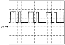
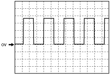
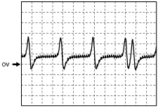
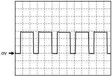
Inspection Using An Oscilloscope (Reference)
CKP signal
dbg140awb104
|
Vehicle speed signal
dbg140awb184
|
Injection pump (speed sensor) signal
dbg140awb102
|
Electronic governor signal
dbg140awb103
|
Using M-MDS
1. Connect the M-MDS to the DLC-2. (See ON-BOARD DIAGNOSTIC TEST [WL-3].)
2. Measure the PID value.
3. Turn the engine switch to the ON position (Engine off).
PID Monitor Table (Reference)
|
Monitor item (Definition) |
Unit/Condition |
Condition/Specification |
Action |
PCM terminal |
|||||
|---|---|---|---|---|---|---|---|---|---|
|
ACCS (Air conditioning compressor cycling switch)
|
ON/OFF
|
Engine switch is ON: OFF
A/C switch is ON at idle: ON
|
Inspect following PIDs: TP, ECT, ACSW, CPP/PNP, VSS, STARTER.
Inspect A/C relay.
|
4L
|
|||||
|
ACSW (A/C switch)
|
ON/OFF
|
A/C switch is ON with engine switch ON: ON
A/C switch is OFF with engine switch ON: OFF
|
Inspect refrigerant pressure switch.
|
3C
|
|||||
|
ARPMDES (Target engine speed)
|
rpm
|
A/C ON: 750 rpm
Other: 720 rpm
|
Inspect A/C switch.
|
—
|
|||||
|
BARO (Barometric pressure)
|
kPa
|
Bar
|
psi
|
Elevation 0—400 m {0—1310 ft}: 100—103 kPa {1.00—1.03 Bar, 14.5—14.9 psi}
|
Replace PCM.
|
—
|
|||
|
V
|
Elevation 0—400 m {0—1310 ft}: approx. 4.0 V
|
||||||||
|
CPP/PNP (Neutral/clutch pedal position)
|
ON/OFF
|
Neutral position or clutch pedal is depressed: ON
Others: OFF
|
Inspect neutral switch and CPP switch.
|
1D
|
|||||
|
CSP (Control sleeve signal voltage)
|
V
|
Engine switch is wiring harness: below 1.0 V
Engine switch is ON or idle: approx. 2.5 V
|
Inspect control sleeve (CS) sensor.
|
1Q
|
|||||
|
ECT (Engine coolant temperature)
|
°C
|
°F
|
ECT is 20°C {68°F}: 20°C {68°F}
ECT is 85°C {185°F}: 85°C {185°F}
|
Inspect ECT sensor.
|
1T
|
||||
|
V
|
ECT is 20°C {68°F}: 3.0—3.2 V
ECT is 85°C {185°F}: 0.7—0.9 V
|
||||||||
|
EGRA (EGR solenoid valve (vent))
|
%
|
Engine switch is ON: 0—100%
Idle: 0—100%
|
Inspect following PIDs: ECT, TP, IDLE SW, MAF, IAT, RPM, EGRVP.
Inspect EGR solenoid valve (vent).
|
4Q
|
|||||
|
EGRV (EGR solenoid valve (vacuum))
|
%
|
Engine switch is ON: 0—100%
Idle: 0—100%
|
Inspect following PIDs: ECT, TP, IDLE SW, MAF, IAT, RPM, EGRVP.
Inspect EGR solenoid valve (vent).
|
4T
|
|||||
|
EGRVP (EGR valve position)
|
V
|
Engine switch is ON: Below 1.0
Idle: above 3.0 V
|
Inspect EGR valve position sensor.
|
1F
|
|||||
|
FLT (Fuel temperature sensor)
|
°C
|
°F
|
Fuel temperature is 20°C {68°F}: 20°C {68°F}:
|
Inspect fuel temperature sensor.
|
1L
|
||||
|
FLT V (Fuel temperature signal voltage)
|
V
|
Fuel temperature is 20°C {68°F}: 2.4—2.6 V
Fuel temperature is 70°C {158°F}: 0.7—0.9 V
|
Inspect fuel temperature sensor.
|
1L
|
|||||
|
FSOV (Fuel cut solenoid valve)
|
ON/OFF
|
Idle: ON
Engine switch is ON: ON
Engine speed is above 5,100 rpm: OFF
DTC P1182, P0251, P0606, P1226 is detected: OFF
|
Perform applicable DTC troubleshooting
|
4W
|
|||||
|
GPC (Glow plug relay)
|
ON/OFF
|
ECT below 60°C {140°F}
• For 15 s after engine switch ON: ON
• After 15 s elapse from engine switch ON: OFF
• For 6.5 s—10 min after engine started: ON
• After 6.5 s—10 min elapse from engine started: OFF
ECT above 60°C {140°F}
• For 6.5 s after engine switch ON: ON
• After 6.5 s elapse from engine switch ON: OFF
|
Inspect following PIDs: ECT, VSS, VPWR.
Inspect glow plug relay.
|
4V
|
|||||
|
GP_LMP
(Glow indicator light)
|
ON/OFF
|
For 4s after engine switch ON (ECT is 20°C {68°F}): ON
|
Inspect instrument cluster.
|
4S
|
|||||
|
IAT (Intake air temperature (IAT sensor No.1))
|
°C
|
°F
|
IAT is 20°C {68°F}: 20°C {68°F}
IAT is 30°C {86°F}: 30°C {86°F}
|
Inspect IAT sensor No.1.
|
1J
|
||||
|
V
|
IAT is 20°C {68°F}: 2.3—2.5 V
IAT is 30°C {86°F}: 1.8—2.0 V
|
||||||||
|
IAT2 (Intake air temperature (IAT sensor No.2))
|
°C
|
°F
|
IAT is 20°C {68°F}: 20°C {68°F}
IAT is 30°C {86°F}: 30°C {86°F}
|
Inspect MAF sensor/IAT sensor No.2.
|
3D
|
||||
|
V
|
IAT is 20°C {68°F}: 2.3—2.5 V
IAT is 30°C {86°F}: 1.8—2.0 V
|
||||||||
|
IDLE SW (Idle switch)
|
ON/OFF
|
Accelerator pedal is released: ON
Other: OFF
|
Inspect idle switch.
|
3O
|
|||||
|
MAF (mass airflow amount)
|
V
|
Engine switch is ON: below 1.0 V
Idle: 1.6—2.0 V
|
Inspect MAF sensor/IAT sensor No.2.
|
4E
|
|||||
|
MAINRLY (Main relay)
|
ON/OFF
|
Engine switch is ON: ON
Other: OFF
|
Inspect engine switch.
|
3A
|
|||||
|
MAP (Boost sensor)
|
kPa
|
Bar
|
psi
|
Idle: 101kPa {1.01 Bar, 14.7psi}
|
Inspect boost sensor.
|
1P
|
|||
|
V
|
Idle: approx. 2.6V
|
||||||||
|
MIL (Malfunction indicator lamp)
|
ON/OFF
|
Engine switch is ON: ON
Idle: OFF
|
Perform applicable DTC troubleshooting
|
—
|
|||||
|
RPM (Engine speed)
|
rpm
|
A/C ON: 725—775rpm
Other: 695—745rpm
|
Inspect following PIDs: TP, MAP, RPM
|
1H
|
|||||
|
SELTESTDTC (Diagnostic trouble codes)
|
—
|
—
|
Perform applicable DTC troubleshooting
|
—
|
|||||
|
STARTER (Engine switch)
|
ON/OFF
|
Engine switch at START: ON
Other: OFF
|
Inspect engine switch.
|
1U
|
|||||
|
TCV (Timer control valve signal)
|
%
|
Idle: 99.6 %
Engine speed 2,000 rpm: 35 %
|
Inspect timer control valve
|
4U
|
|||||
|
TPS (Timer position sensor signal)
|
%
|
Engine switch is ON: 0%
Idle: 100%
|
Inspect timer position sensor.
|
1K
|
|||||
|
TEST (TEN terminal (in DLC))
|
ON/OFF
|
Terminal TEN (DLC) is shorted to ground: ON
Terminal TEN (DLC) is open: OFF
|
Inspect wiring from DLC terminal TEN to PCM terminal 2A.
|
2A
|
|||||
|
TP (Accelerator pedal position sensor No.1)
|
V
|
Accelerator pedal is depressed: 3.4—3.8 V
Accelerator pedal is released:0.5—0.7 V
|
Inspect accelerator pedal position sensor.
|
1R
|
|||||
|
TP2 V (Accelerator pedal position sensor No.2)
|
V
|
Accelerator pedal is depressed: 3.4—3.8 V
Accelerator pedal is released: 0.5—0.7 V
|
Inspect accelerator pedal position sensor.
|
2C
|
|||||
|
VPWR (Battery positive voltage)
|
V
|
Engine switch is ON: B+
Other: below 1.0 V
|
Inspect main relay.
|
4C
|
|||||
|
VSS (Vehicle speed)
|
km/h
|
mph
|
Vehicle speed is 20 km/h {12.5 mph}: 20 km/h {12.5 mph}
Vehicle speed is 40 km/h {25 mph}: 40 km/h {25 mph}
|
Inspect Instrument cluster.
|
1N
|
||||