TIMER POSITION SENSOR INSPECTION [WL-3]
id0140b5809600
-
Note
-
• Perform the following inspection only when directed.
Resistance Inspection
1. Disconnect the negative battery cable.
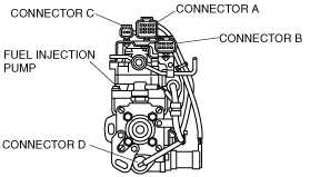
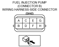
2. Disconnect the fuel injection pump connector B.
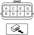
3. Inspect the resistance between the terminals under the following condition.
-
• Consult authorized BOSCH parts distributor for repair if the timer position sensor is possibly malfunctioning:
• If as specified, carry out the “Circuit Open/Short Inspection”.
Specification
|
Terminal
|
Resistance (ohm) [25 °C{77 °F}]
|
|
A—B
|
82—84
|
|
A—C
|
82—84
|
|
B—C
|
164—168
|
Circuit Open/Short Inspection
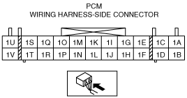
1. Disconnect the PCM connector. (See PCM REMOVAL/INSTALLATION [WL-3].)
2. Inspect for an open or short circuit in the following wiring harnesses.
-
• If there is an open or short circuit, repair or replace wiring harnesses.
Open circuit
• Power circuit (fuel injection pump connector B terminal C and PCM connector terminal 1I)
• Signal circuit (fuel injection pump connector B terminal A and PCM connector terminal 1K)
• Ground circuit (fuel injection pump connector B terminal B and PCM connector terminal 1G)
Short circuit
• Fuel injection pump connector B terminal C and PCM connector terminal 1I short to ground
• Fuel injection pump connector B terminal A and PCM connector terminal 1K short to ground
• Fuel injection pump connector B terminal A and PCM connector terminal 1K short to power supply
• Fuel injection pump connector B terminal B and PCM connector terminal 1G short to power supply