 |
absggw00001678
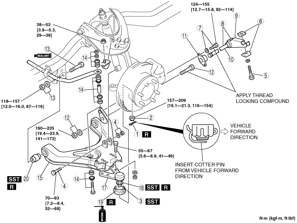
TORSION BAR SPRING AND LOWER ARM REMOVAL/INSTALLATION [4x2 (HIGH CLEARANCE MODEL), 4x4]
id0213008030a6
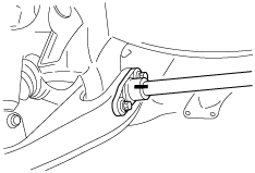
1. Remove the ABS sensor wiring harness brackets installed to the upper arm and steering knuckle, then move aside the ABS sensor.
absggw00001678
|
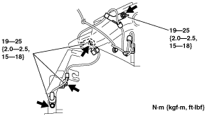
2. Remove in the order indicated in the table.
3. Install in the reverse order of removal.
4. Inspect the vehicle height and adjust it as necessary. (See VEHICLE HEIGHT ADJUSTMENT [4x4].)
5. Inspect the front wheel alignment as necessary. (See FRONT WHEEL ALIGNMENT [4x4].)
absggw00001679
|
|
1
|
Cotter pin
|
|
2
|
Nut
|
|
3
|
Front lower arm ball joint
|
|
4
|
Shock absorber lower bolt and nut
|
|
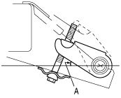
5
|
Anchor bolt
|
|
6
|
Anchor swivel
|
|
7
|
Bolt and washer
|
|
8
|
Torsion bar spring component
|
|
9
|
Anchor arm
(See Anchor Arm Removal Note.)
(See Anchor Arm Installation Note.)
|
|
10
|
Torsion bar spring
|
|
11
|
Torque plate
|
|
12
|
Lower arm spindle (rear), washer and nut
|
|
13
|
Lower arm spindle (front), washer and nut
|
|
14
|
Stabilizer bolt, bushing, retainer, spacer and nut
|
|
15
|
Front lower arm
|
|
16
|
Bound stopper
|
|
17
|
Front lower arm ball joint
|
|
18
|
Clip
|
|
19
|
Dust boot
|
|
20
|
Front lower arm bushing
|
Anchor Arm Removal Note
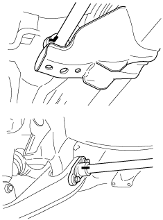
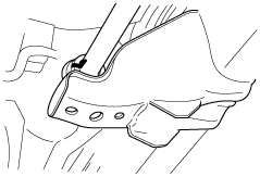
1. Mark the anchor arm and body for reference during installation.
absggw00001680
|
Torsion Bar Spring Removal Note
1. Mark the torsion bar spring and anchor arm, and torsion bar spring and torque plate for reference during installation.
absggw00001681
|
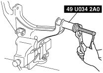
Front Lower Arm Bushing Removal Note
1. Remove the front lower arm bushing using the SST.
absggw00001682
|
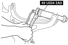
Front Lower Arm Bushing Installation Note
1. Apply soapy water to the new bushing.
2. Install the bushing using the SST.
absggw00001683
|
Torsion Bar Spring Installation Note
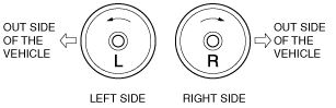
1. Before installation, check the identification mark on the end of the torsion bar spring.
absggw00001684
|
2. Align the marks made during removal, and connect the torsion bar spring to the torque plate.
absggw00001685
|
Anchor Arm Installation Note
1. Align the marks made during removal, and install the anchor arm onto the torsion bar spring.
absggw00001686
|
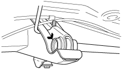
Anchor Bolt Installation Note
1. Install the anchor bolt, and tighten it until the marks made during removal are aligned.
absggw00001687
|
absggw00001688
|