|
absggw00001642
WHEEL HUB, STEERING KNUCKLE REMOVAL/INSTALLATION [4x2 (EXCEPT HIGH CLEARANCE MODEL)]
id0311008004a3
1. Remove in the order indicated in the table.
2. Install in the reverse order of removal.
absggw00001642
|
|
1
|
ABS wheel-speed sensor (with ABS)
|
|
2
|
Clip
|
|
3
|
Hub cap
|
|
4
|
Cotter pin
|
|
5
|
Set cover
|
|
6
|
Locknut
|
|
7
|
Washer
|
|
8
|
Brake caliper component
|
|
9
|
Hub and disc plate component
|
|
10
|
Dust cover
|
|
11
|
Tie-rod end
|
|
12
|
Knuckle arm
|
|
13
|
Lower arm ball joint
|
|
14
|
Upper arm ball joint
|
|
15
|
Steering knuckle
|
|
16
|
Disc plate
|
|
17
|
Wheel hub
|
|
18
|
Hub bolt
(See Hub Bolt Installation Note.)
|
|
19
|
Outer bearing inner race
|
|
20
|
Oil seal
(See Oil Seal Installation Note.)
|
|
21
|
Inner bearing inner race
|
|
22
|
Inner bearing outer race
|
|
23
|
Outer bearing outer race
|
|
24
|
ABS sensor rotor (with ABS)
|
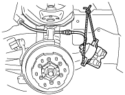
Brake Caliper Component Removal Note
1. Remove the brake caliper component installation bolt, and suspend it with a cable in place out of the way.
absggw00001643
|
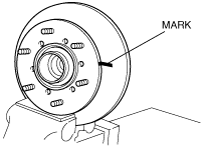
Disc Plate, Wheel Hub, Hub Bolt Removal Note
1. After putting markings on the disc plate and the wheel hub, remove the bolt and disassemble the plate and hub.
absggw00001644
|
2. Remove the hub bolt using a press as necessary.
Inner Bearing Outer Race, Outer Bearing Outer Race Removal Note
1. Remove the bearing outer race using a suitable round bar and a hammer. For other side, reverse the wheel hub and remove the outer race.
absggw00001645
|
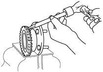
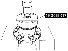
ABS Sensor Rotor Removal Note
1. Remove the sensor rotor using a chisel.
absggw00001646
|
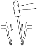
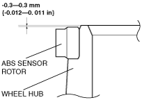
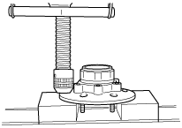
ABS Sensor Rotor Installation Note
1. Set the SST shown in the figure.
absggw00001647
|
2. Press the new sensor rotor in unit flush with the end of the wheel hub using the SST and a press.
absggw00001648
|
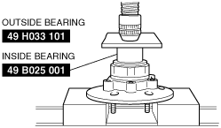
Outer Bearing Outer Race, Inner Bearing Outer Race Installation Note
1. Install the bearing outer race using the SSTs and a press. For other side, reverse the wheel hub and install the outer race.
absggw00001649
|
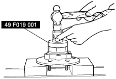
Oil Seal Installation Note
1. After inserting the bearing in the hub, tap in the oil seal until it is flush with the hub end surface using the SST.
absggw00001650
|
2. Apply grease to the oil seal lip.
Hub Bolt Installation Note
1. Press new hub bolts into the wheel hub using a press.
absggw00001651
|
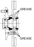
Hub And Disc Plate Component Installation Note
1. Apply grease to the areas indicated in the figure.
absggw00001652
|
2. Install the hub and disc plate component, then adjust the preload. (See WHEEL HUB, STEERING KNUCKLE INSPECTION [4x2 (EXCEPT HIGH CLEARANCE MODEL)].)