 |
absggw00001996
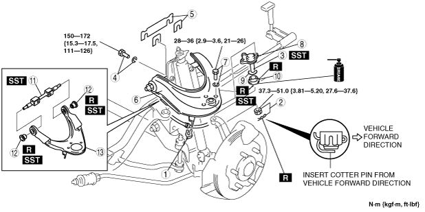
FRONT UPPER ARM REMOVAL/INSTALLATION
id021300801900
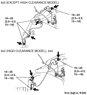
1. Remove the ABS sensor wiring harness brackets installed to the upper arm and steering knuckle, then move aside the ABS sensor.
absggw00001996
|
2. Remove in the order indicated in the table.
3. Install in the reverse order of removal.
4. Inspect the front wheel alignment and adjust it as necessary. (See FRONT WHEEL ALIGNMENT [4x2]) (See FRONT WHEEL ALIGNMENT [4x4].)
absggw00001997
|
|
1
|
Brake hose bracket
|
|
2
|
Cotter pin and nut
|
|
3
|
Front upper arm ball joint
|
|
4
|
Bolt and washer
|
|
5
|
Adjustment shim
(See Adjustment Shim Removal Note.)
|
|
6
|
Front upper arm component
|
|
7
|
Bolt and washer
|
|
8
|
Front upper arm ball joint
|
|
9
|
Clip
(See Clip Installation Note.)
|
|
10
|
Dust boot
|
|
11
|
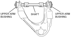
Shaft
|
|
12
|
Front upper arm bushing
|
|
13
|
Front upper arm
|
Front Upper Arm Ball Joint Removal Note
1. Separate the upper arm ball joint from the knuckle arm using the SST.
absggw00001998
|
Adjustment Shim Removal Note
1. Note the number, amount and position of the shims so that they are reinstalled in the correct positions.
Shaft And Front Upper Arm Bushing Removal Note
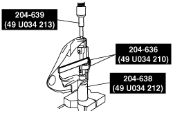
1. Install the SSTs to the front upper arm.
absggw00001999
|
2. Set the front upper arm assembled in Step 1. to the press, then install the SSTs and remove the shaft and upper arm bushings.
absggw00002000
|
3. Remove the front upper arm bushing remaining on the front upper arm using the SSTs.
absggw00002001
|
4. Remove the front upper arm bushing remaining on the shaft using the SSTs.
absggw00002002
|
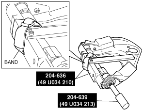
Front Upper Arm Bushing And Shaft Installation Note
1. Temporarily install the shaft and front upper arm bushings to the front upper arm.
absggw00002003
|
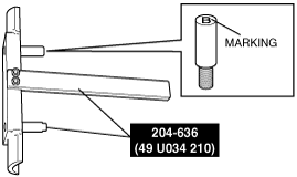
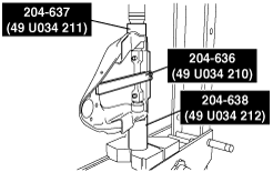
2. Assemble the SSTs (49 U034 210).
absggw00002013
|
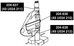
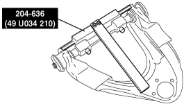
3. Install the SSTs assembled in Step 2. to the front upper arm as shown in the figure.
absggw00002005
|
absggw00002007
|
4. Press fit either one of the front upper arm bushings using a press and the SSTs.
absggw00002006
|
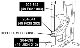
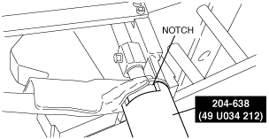
5. Press fit the other upper arm bushing using a press and the SSTs.
absggw00002008
|
Clip Installation Note
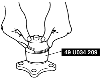
1. Install the SST to the ball joint stud with the stud stands straight up.
2. Install the clip in the dust boot groove using the SST.
absggw00002009
|