 |
absggw00000881
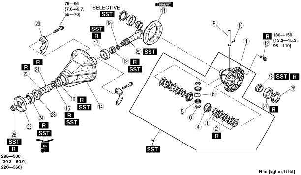
REAR DIFFERENTIAL ASSEMBLY [LSD (LIMITED SLIP DIFFERENTIAL)]
id0314008006a2
1. Assemble in the order indicated in the table.
absggw00000881
|
|
1
|
Differential case
|
|
2
|
LSD clutches
|
|
3
|
Side gear thrust washer
|
|
4
|
Side gear
|
|
5
|
Pinion gear
|
|
6
|
Pinion gear thrust washer
|
|
7
|
Limited slip differential component
|
|
8
|
Thrust block
|
|
9
|
Pinion shaft
|
|
10
|
Knock pin
|
|
11
|
Ring gear
|
|
12
|
Bolt
|
|
13
|
Side bearing inner race
|
|
14
|
Differential carrier
|
|
15
|
Oil baffle
|
|
16
|
Front bearing outer race
|
|
17
|
Rear bearing outer race
|
|
18
|
Adjusting shim
(See Adjusting Shim Assembly Note.)
|
|
19
|
Rear bearing inner race
|
|
20
|
Drive pinion
(See Drive Pinion Assembly Note.)
|
|
21
|
Collapsible spacer
|
|
22
|
Front bearing inner race
|
|
23
|
Thrust washer
|
|
24
|
Oil seal
|
|
25
|
Companion flange
|
|
26
|
Locknut
|
|
27
|
Side bearing outer race
|
|
28
|
Adjusting shim
|
|
29
|
Bearing cap
|
Adjusting Shim Assembly Note
Pinion height adjustment [F2, G6, WLT-1, WLT-2]
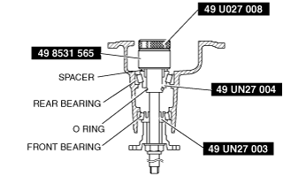
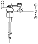
1. Assemble the spacer, rear bearing inner race and SST (49 UN27 004) on to the SST (49 8531 565). Secure the collar with the O-ring, then install this to the carrier.
arnffw00000257
|
2. Assemble the front bearing inner race, SST (49 UN27 003), companion flange, washer and nut to the SST (49 8531 565).
3. Tighten the nut to the extent that the SST (49 8531 565) can be turned by hand.
4. Place the SST on the surface plate and set the dial indicator to zero.
arnffw00000279
|
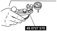
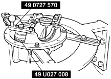
5. Place the SST (49 U027 008) on top of the SST (49 8531 565), and then set the SST (49 0727 570) on top of the SST (49 U027 008).
6. Place the measuring probe of the dial indicator so that it contacts the place where the side bearing is installed in the carrier, then measure left and right side of the lower position.
arnffw00000259
|
7. Add the two (left and right) values obtained by the measurements taken in Step 6 and then divide the total by 2. From this sum, subtract the sum of the number inscribed on the end of the drive pinion divided by 100. (If there is no figure inscribed, use 0.)
8. Subtract 3 from measurement taken in Step 7. This is the pinion height adjustment value.
arnffw00000281
|
Pinion height adjustment [WL-C, WE-C]
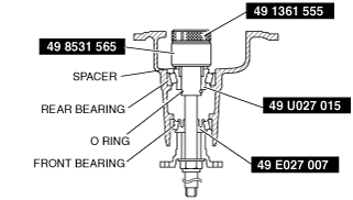
1. Assemble the spacer, rear bearing inner race and SST (49 U027 015) on to the SST (49 8531 565). Secure the collar with the O-ring, then install this to the carrier.
absggw00000882
|
2. Assemble the front bearing inner race, SST (49 E027 007), companion flange, washer and nut to the SST (49 8531 565).
3. Tighten the nut to the extent that the SST (49 8531 565) can be turned by hand.
4. Place the SST on the surface plate and set the dial indicator to zero.
absggw00000883
|
5. Place the SST (49 1361 555) on top of the SST (49 8531 565), and then set the SST (49 0727 570) on top of the SST (49 1361 555).
6. Place the measuring probe of the dial indicator so that it contacts the place where the side bearing is installed in the carrier, then measure left and right side of the lower position.
absggw00000884
|
7. Add the two (left and right) values obtained by the measurements taken in Step 6 and then divide the total by 2. From this sum, subtract the sum of the number inscribed on the end of the drive pinion divided by 100. (If there is no figure inscribed, use 0.) This is the pinion height adjustment value.
absggw00000885
|
Drive Pinion Assembly Note
Drive pinion preload adjustment
1. Assemble the following parts to the drive pinion.
2. Adjust the preload of the drive pinion bearing as follows:
absggw00000886
|
Limited Slip Differential Component Assembly Note
1. Assemble the retainer clips to the ears of the clutch plates. Make sure both clips are completely assembled or seated onto the ears of the clutch plates.
2. Place the differential case on a bench. Assemble the clutch pack and side gear into the differential case. Make sure the clutch pack stays assembled to the splines of side gear, and the retainer clips differential case.
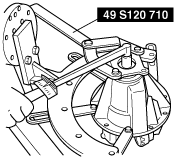
3. Install the SSTs to the differential case.
absggw00000887
|
4. With tools assembled to the differential case, position the differential case onto the axle shaft by aligning the splines of the differential side gear with those of the axle shaft.
5. Position both pinion gears opposite one another through the openings in the differential case. Align holes of the differential pinion gears with each other. Hold the pinion gears by hand.
6. Tighten the SST so the side gears move away condition.
7. While holding the pinion gears in place, insert SST into the hole of pinion shaft in the differential case. Pull on the SST rotating differential case allowing the differential pinion gears to rotate and enter into the differential case.
absggw00000888
|
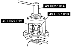
8. Adjust the SST by very slightly loosening or tightening until the required load is applied to allow the side gears and pinion gears to rotate.
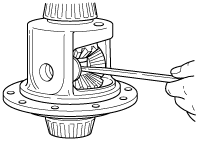
9. Rotate the differential case until the holes of both pinion gears are aligned with those of the differential case.
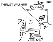
10. Apply torque to the SST for clearance to assemble the differential thrust washers.
absggw00000889
|
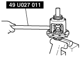
11. Assemble thrust washers into the differential case. Use a very small screwdriver or shim stock to push the washers into place.
absggw00000890
|