 |
absggw00002327
PROPELLER SHAFT DISASSEMBLY/ASSEMBLY [FRONT (R15MX-D)]
id0315008004e1
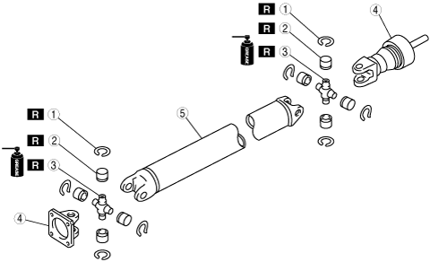
1. Disassemble in the order indicated in the table.
2. Assemble in the reverse order of disassembly.
absggw00002327
|
|
1
|
Snap ring
(See Snap Ring Disassembly Note.)
|
|
2
|
Bearing cup
|
|
3
|
Spider
|
|
4
|
Yoke
|
|
5
|
Propeller shaft
|
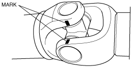
Snap Ring Disassembly Note
1. Mark the yoke end propeller shaft for proper reassembly.
absggw00002304
|
2. Clamp the propeller shaft in a vise.
3. Remove the snap ring.
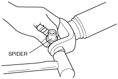
Bearing Cup, Spider Disassembly Note
1. Push one bearing cup out of the propeller shaft by tapping the yoke with a plastic hammer.
absggw00002305
|
2. Remove the opposite bearing cup in the same manner.
3. Separate the propeller shaft and yoke.
4. Clamp the yoke in a vise.
5. Remove the bearing cups and the spider from the yoke in the same manner as in Steps 1 and 2.
Spider, Bearing Cup, Snap Ring Assembly Note
1. Verify that the inside of the bearing cup is filled with 1.15—1.45 g {0.04—0.05 oz} grease. Add the specified amount of disulphide molybdem grease as necessary.
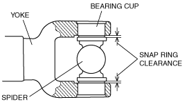
2. Set the new spider into the yoke and tap in a new bearing cup until the snap ring groove is exposed.
absggw00002306
|
3. Measure the snap ring clearance, then select and install two new snap rings of equal thickness.
absggw00002328
|
4. Install the remaining bearing cups and snap rings as in steps 1—3.
5. Inspect the propeller shaft initial torque. (See PROPELLER SHAFT INSPECTION.)