|
1
|
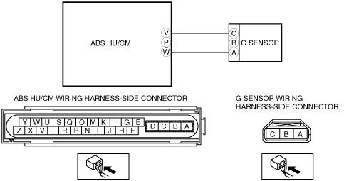
INSPECT G SENSOR POWER SUPPLY CIRCUIT FOR OPEN CIRCUIT
• Turn ignition switch or engine switch to ON (engine OFF).
• Measure voltage between G sensor terminal C (harness side)and ground.
• Is voltage B+?
|
Yes
|
Go to the next step.
|
|
No
|
Repair or replace harness for open circuit between G sensor terminal C and ignition switch or engine switch, then go to Step 7.
|
|
2
|
INSPECT G SENSOR GROUND CIRCUIT FOR OPEN CIRCUIT
• Turn ignition switch or engine switch to OFF.
• Disconnect ABS HU/CM and G sensor connectors.
• Inspect continuity between ABS HU/CM terminal W (harness side) and G sensor terminal A (harness side).
• Is there continuity?
|
Yes
|
Go to the next step.
|
|
No
|
Repair or replace harness for open circuit between ABS HU/CM terminal W and G sensor terminal A, then go to Step 7.
|
|
3
|
INSPECT G SENSOR SIGNAL CIRCUIT FOR OPEN CIRCUIT
• Inspect continuity between ABS HU/CM terminal P (harness side) and G sensor terminal B (harness side).
• Is there continuity?
|
Yes
|
Go to the next step.
|
|
No
|
Repair or replace harness for open circuit between ABS HU/CM terminal P and G sensor terminal B, then go to Step 7.
|
|
4
|
INSPECT G SENSOR SIGNAL CIRCUIT FOR SHORT TO POWER
• Turn ignition switch or engine switch to ON (engine OFF).
• Measure voltage between ABS HU/CM terminal P (harness side) and ground.
• Is voltage B+?
|
Yes
|
Repair or replace harness for short to power circuit between ABS HU/CM terminal P and G sensor terminal B, then go to Step 7.
|
|
No
|
Go to the next step.
|
|
5
|
INSPECT G SENSOR SIGNAL CIRCUIT FOR SHORT TO GROUND
• Turn ignition switch or engine switch to OFF.
• Inspect continuity between ABS HU/CM terminal P (harness side) and ground.
• Is there continuity?
|
Yes
|
Repair or replace harness for short to ground circuit between ABS HU/CM terminal P and G sensor terminal B, then go to Step 7.
|
|
No
|
Go to the next step.
|
|
6
|
INSPECT G SENSOR
• Is it normal?
|
Yes
|
Go to the next step.
|
|
No
|
Replace the G sensor, then go to next step.
|
|
7
|
VERIFY DTC TROUBLESHOOTING COMPLETED
• Make sure to reconnect all disconnected connectors.
• Clear the DTC from the memory.
• Are the same DTCs present?
|
Yes
|
Replace the ABS HU/CM, then go to next step.
|
|
No
|
Go to the next step.
|
|
8
|
VERIFY AFTER REPAIR PROCEDURE
• Are any other DTCs present?
|
Yes
|
Go to the applicable DTC inspection.
|
|
No
|
DTC troubleshooting completed.
|