DTC 24
Open or short circuit in wiring harness between immobilizer unit and PCM
POSSIBLE CAUSE
• Defective immobilizer unit
• Defective PCM
• Poor connection of connector
• Defective wiring harness
DTC 24 [IMMOBILIZER SYSTEM]
id0902e4904700
WE-C, WL-3, WL-C
|
DTC 24 |
Open or short circuit in wiring harness between immobilizer unit and PCM |
|---|---|
|
POSSIBLE CAUSE
|
• Defective immobilizer unit
• Defective PCM
• Poor connection of connector
• Defective wiring harness
|
|
|
Diagnostic procedure
|
STEP |
INSPECTION |
ACTION |
|
|---|---|---|---|
|
1
|
INSPECT CONNECTOR CONNECTION
• Are both immobilizer unit and PCM connectors connected properly?
|
Yes
|
Go to next step.
|
|
No
|
Connect connectors properly.
|
||
|
2
|
INSPECT COMMUNICATION CIRCUIT FOR CONTINUITY
• Disconnect immobilizer unit and PCM connectors.
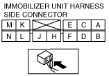
• Is there continuity between immobilizer unit connector terminal A and following PCM connector terminal?
|
Yes
|
Go to next step.
|
|
No
|
Repair wiring harness between PCM and immobilizer unit.
|
||
|
3
|
INSPECT IMMOBILIZER UNIT FOR SHORT TO GND
• Is there continuity between immobilizer unit connector terminal A and ground?
|
Yes
|
Repair short circuit in wiring harness between PCM and immobilizer unit.
|
|
No
|
Go to next step.
|
||
|
4
|
INSPECT COMMUNICATION CIRCUIT
• Connect PCM connector.
• Turn engine switch to ON position.
• Measure voltage at immobilizer unit connector terminal A.
• Is voltage more than 10 V?
|
Yes
|
Replace immobilizer unit and reprogram immobilizer system.
|
|
No
|
Replace PCM and reprogram immobilizer system.
|
||
WLT-2
|
DTC 24 |
Open or short circuit in wiring harness between immobilizer unit and DDS1 |
|---|---|
|
POSSIBLE CAUSE
|
• Defective immobilizer unit
• Defective DDS1
• Poor connection of connector
• Defective wiring harness
|
|
|
Diagnostic procedure
|
STEP |
INSPECTION |
ACTION |
|
|---|---|---|---|
|
1
|
INSPECT CONNECTOR CONNECTION
• Are both immobilizer unit and FIP connectors connected properly?
|
Yes
|
Go to next step.
|
|
No
|
Connect connectors properly.
|
||
|
2
|
INSPECT COMMUNICATION CIRCUIT FOR CONTINUITY
• Disconnect FIP connector.
• Turn engine switch to ON position.
• Measure voltage at FIP connector terminal H.
• Is voltage more than 10 V?
|
Yes
|
Go to Step 5.
|
|
No
|
Go to next step.
|
||
|
3
|
INSPECT COMMUNICATION CIRCUIT FOR CONTINUITY
• Disconnect immobilizer unit and FIP connectors.
• Is there continuity between immobilizer unit connector terminal A and FIP connector terminal H?
|
Yes
|
Go to next step.
|
|
No
|
Repair wiring harness between DDS1 and immobilizer unit.
|
||
|
4
|
INSPECT IMMOBILIZER UNIT FOR SHORT TO GND
• Is there continuity between immobilizer unit connector terminal A and ground?
|
Yes
|
Repair for short circuit in wiring harness between DDS1 and immobilizer unit.
|
|
No
|
Go to next step.
|
||
|
5
|
INSPECT POWER CIRCUIT FOR OPEN CIRCUIT TO DDS1
• Turn engine switch to ON position.
• Measure voltage at FIP connector terminal G.
• Is voltage more than 10 V?
|
Yes
|
Go to next step.
|
|
No
|
Repair wiring harness between ENGINE 15 A fuse and DDS1.
|
||
|
6
|
INSPECT DDS1 FOR SHORT TO GND
• Turn engine switch to LOCK position.
• Disconnect FIP connector.
• Is there continuity between FIP connector terminal F and ground?
|
Yes
|
Go to next step.
|
|
No
|
Repair wiring harness between DDS1 and ground.
|
||
|
7
|
INSPECT INNER CIRCUIT OF IMMOBILIZER UNIT
• Replace immobilizer unit and reprogram immobilizer system.
• Dose engine start?
|
Yes
|
Immobilizer unit was defective.
|
|
No
|
Replace DDS1 and reprogram immobilizer system.
|
||