1. Component views
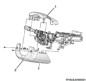
Steering column
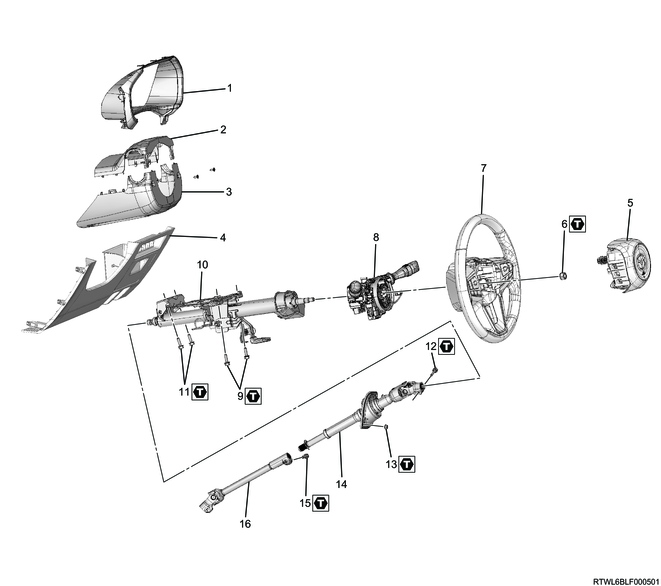
Part name
- Meter cluster
- Steering cowl upper
- Steering cowl lower
- Instrument panel driver-side lower cover
- Driver airbag
- Nut
- Steering wheel
- Combination switch and SRS coil
- Bolt
- Steering column
- Bolt
- Bolt
- Nut
- Second steering shaft
- Bolt
- Lower second steering shaft
Tightening torque
6: 35 N・m { 3.6 kgf・m / 26 lb・ft }
9: 20 N・m { 2 kgf・m / 15 lb・ft }
11: 20 N・m { 2.0 kgf・m / 15 lb・ft }
12: 31 N・m { 3.2 kgf・m / 23 lb・ft }
13: 6.5 N・m { 0.7 kgf・m / 58 lb・in }
15: 31 N・m { 3.2 kgf・m / 23 lb・ft }
2. Steering column installation
1) Install the second steering shaft to the steering column according to the alignment marks placed during removal.
Tightening torque: 31 N・m { 3.2 kgf・m / 23 lb・ft }
2) Temporarily tighten the steering column to vehicle.
Note
- Pass the second steering shaft through the hole of the dash panel.
3) Securely tighten the steering column to vehicle.
Tightening torque: 20 N・m { 2.0 kgf・m / 15 lb・ft }
4) Install the dust cover to vehicle.
Tightening torque: 6.5 N・m { 0.7 kgf・m / 58 lb・in }
Note
- Install the dust cover with the long hole facing upward.

Legend
- Long hole
3. Steering shaft installation
1) Install the lower second steering shaft to the second steering shaft according to the alignment marks placed during removal.
Tightening torque: 31 N・m { 3.2 kgf・m / 23 lb・ft }
Caution
- Install while it makes contact with the yoke.
- Tighten the bolt by hand until seated and final tighten.
- Tighten the tire while it is in contact with the ground.
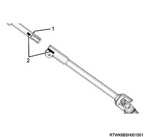
Legend
- Yoke
- Alignment mark
2) Connect the universal joint to the power steering unit according to the alignment marks placed during removal.
Tightening torque: 31 N・m { 3.2 kgf・m / 23 lb・ft }
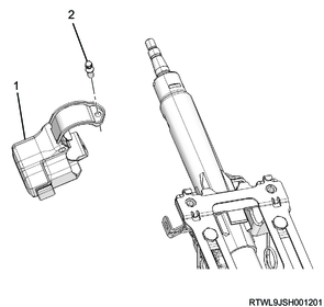
4. Steering lock installation
1) Align the lock bar of the steering lock with the steering shaft side mounting position to install.
Legend
- Lock bar
2) Install the steering lock to the steering shaft.
Caution
- Do not damage the ICU antenna coil portion.
- Tighten the shear bolt until the head of the bolt is twisted off.
Models without the passive entry and start system

Legend
- Steering lock
- Shear bolt
- ICU antenna coil portion
Models with the passive entry and start system
Legend
- Steering lock
- Shear bolt
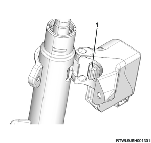
5. Combination switch installation
1) Install the combination switch to the steering shaft.
Note
- Align the protrusion of the combination switch with the notch of the steering shaft to install.
Legend
- Combination switch
- Metal band
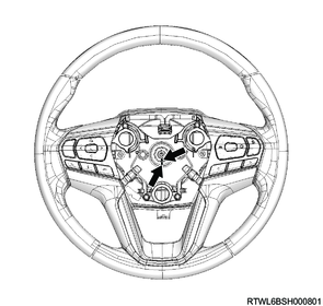
2) Connect the connector to the combination switch.
6. Steering cowl installation
1) Install the steering cowl to the steering shaft.
Tightening torque: 2.5 N・m { 0.25 kgf・m / 22.1 lb・in }
Legend
- Steering upper cowl
- Steering lower cowl
7. Instrument panel driver-side lower cover installation
1. Models without knee airbags
1) Connect the connector to the instrument panel driver-side lower cover.
2) Install the instrument panel driver-side lower cover to the instrument panel.
RHD

Legend
- Instrument panel driver-side lower cover
LHD
Legend
- Instrument panel driver-side lower cover
3) Install the hood lock control lever and fuel filler lid opener lever to the instrument panel driver-side lower cover.
RHD
Legend
- Hood lock control lever
- Fuel filler lid opener lever
- Claw section
LHD
Legend
- Fuel filler lid opener lever
- Hood lock control lever
- Claw section
4) Connect the wire to each lever.
8. Knee air bag installation
1. Models with knee airbags
Refer to "8.Restraints 8B.Airbag Systems knee air bag installation".
9. Steering wheel installation
1) Install the steering wheel to the steering shaft according to the alignment marks placed during removal.
Tightening torque: 35 N・m { 3.6 kgf・m / 26 lb・ft }
Caution
- The steering wheel should never be installed using a hammer or tool that causes shock.
The steering wheel is designed to absorb impact.
10. Driver airbag installation
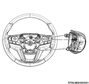
1) Connect the airbag connector to the driver airbag.
2) Connect the horn connector to the driver airbag.

Legend
- Airbag connector
- Horn connector
3) Install the driver airbag to the steering wheel.
Note
- Align each stud of the driver airbag with the steering wheel hole.
4) Press the driver airbag pushing section and install the driver airbag to the steering wheel.
Caution
- Do not allow the harness to get caught.
Note
- Check the sound of each stud engaging with the steering wheel.
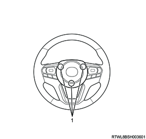
Legend
- Pushing section
11. SRS airbag setting
1. SRS reactivation
Warning
- Never use SRS parts from other vehicles or models.
- Make sure to check the part numbers and use the SRS components intended for the target vehicle.
1) Set the ignition switch to LOCK and remove the key.
Note
- For models with the passive entry and start system, turn the power mode OFF.
2) Make sure that the connectors of the SRS components (SRS airbag, SRS control unit, seat belt with pretensioner, SRS coil, etc.) are fully connected.
3) Install the SRS fuse to the fuse relay box, and connect the battery cable to the negative terminal of the battery.
4) Turn ON the ignition switch and verify that the SRS airbag warning light turns OFF after illuminating for 6 seconds.
Caution
- If the SRS airbag warning light does not operate properly, perform Diagnostic system check - SRS controls.
5) Referring to the following, perform the setting of the front door power window switch with AUTO UP/AUTO DOWN function.
Refer to "9.Body, Cab, Accessories 9T.Glass, Windows, Mirrors front door power window switch setting".
12. Steering angle sensor setting
1. Precautions (ESC specifications)
If the steering angle sensor has been replaced, or if the battery has been disconnected, perform 0-point learning of the steering angle sensor.
2. Steering angle sensor 0-point learning with scan tool (ESC specifications)
Perform 0-point learning of the steering angle sensor while paying attention to the following.
Perform the procedure in a flat location (having a slope of less than 1%).
Do not open or close the door or rock the vehicle during the process.
To prevent vibration due to idling, do not start the engine.
1) Connect the scan tool to the DLC.
2) Turn ON the ignition switch.
3) Select "Learning for Steering Central Position" on the scan tool.
- Diagnostics > Chassis > ABS/ESC > Special Function > Learning for Steering Central Position
4) Perform 0-point learning of the steering angle sensor by following the on-screen instructions.
5) Drive the vehicle and make sure a DTC is not set.
3. Steering angle sensor 0-point learning by vehicle driving (ESC specifications)
1) Drive straight for about 10 seconds at a vehicle speed of 40 km/h (25 mph) or more on a flat road.
2) Drive the vehicle and make sure a DTC is not set.