1. Component views
Injector
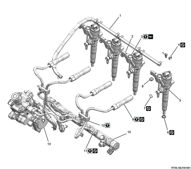
Part name
- Leak-off hose
- Injector clamp
- Injector clamp bolt
- Clip
- Injector
- Gasket
- O-ring
- Pin
- Injection pipe (Injector side)
- Common rail (fuel rail)
- Injection pipe (common rail (fuel rail) side)
- Clip
- Fuel supply pump
Tightening torque
3: 26 N・m { 2.7 kgf・m / 19 lb・ft }
9: 44 N・m { 4.5 kgf・m / 32 lb・ft }
11: 44 N・m { 4.5 kgf・m / 32 lb・ft }
12: 8 N・m { 0.8 kgf・m / 71 lb・in }
2. Injector installation
1) Apply engine oil to the O-ring.
2) Install the O-ring to the injector.
Caution
- Do not damage the O-ring.
3) Clean the cylinder head installation surface and injector.
4) Drop the gasket into the port on the cylinder head side.
Caution
- Do not reuse the gasket.
- Check that the gasket is seated horizontally.
5) Check that the gasket has been inserted based on the nozzle height using the injector.
Caution
- Do not reuse the leak-off pipe or clip.
- Press the injector in perpendicularly to ensure that the gasket is not slanted.
- Do not hold the injector connector.
- Do not forcibly push the gasket into the injector as it will be pushed until it hits the end of the injector during clamp tightening.

Legend
- Injector
- Leak-off pipe
- Clip
- O-ring
- Gasket
6) Install the injector clamp to the injector.

Legend
- Injector
- Bolt
- Injector clamp
7) Apply engine oil to the threaded portions and seating surfaces of the bolts.
8) Install the injector and injector clamp to the cylinder head.
9) Temporarily tighten the injector clamp bolt to the cylinder head.
1. When replacing the injector
Erase the old cylinder number ID code on the Injector ID Code label attached to the cylinder head cover with a black pen, etc.
Label on the cylinder head cover (Sample)
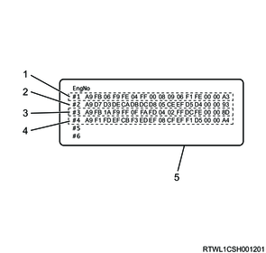
Legend
- No. 1 cylinder Injector ID Code
- No. 2 cylinder Injector ID Code
- No. 3 cylinder Injector ID Code
- No. 4 cylinder Injector ID Code
- Injector ID Code label
1) Record the Injector ID Code of the new injector.
Note
- Record the 32-digit Injector ID plate.
The correct order of the ID codes shown in the following injector illustration is as follows.
A9 D7 D3 DE CA DB DC D8 U5 CE EF D5 D4 00 00 93
Injector (Sample)
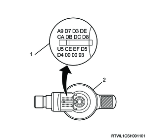
Legend
- Injector ID Code
- Injector
3. Injection pipe installation
1) Apply engine oil to the threaded portions of the sleeve nuts on the injector side, as well as the injector O-rings.
2) Temporarily tighten the injection pipes to the common rail (fuel rail) and injectors by hand until the sleeve nuts can no longer turn.
Caution
- Do not reuse the injection pipe.
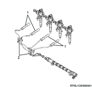
Legend
- Injection pipe
- Clip
3) Temporarily tighten the clip to the injection pipe.
4) Final tighten the injector clamp bolt to the cylinder head.
Tightening torque: 26 N・m { 2.7 kgf・m / 19 lb・ft }
5) Final tighten the injection pipes to the injectors and common rail (fuel rail).
Tightening torque: 44 N・m { 4.5 kgf・m / 32 lb・ft } Injector side
Tightening torque: 44 N・m { 4.5 kgf・m / 32 lb・ft } Common rail (fuel rail) side
6) Securely tighten the clip to the injection pipe.
Tightening torque: 8.0 N・m { 0.8 kgf・m / 71 lb・in }
4. Leak-off pipe installation
1) Install the leak-off pipe to the inlet manifold.
Tightening torque: 25 N・m { 2.5 kgf・m / 18 lb・ft }
2) Connect the 2 leak-off hoses to the leak-off pipe.
3) Connect the 3 vacuum hoses to the vacuum pipe.
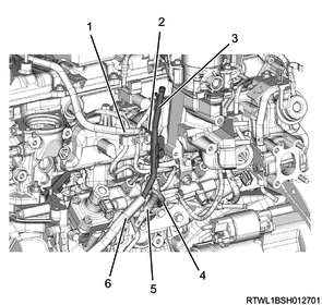
Legend
- Leak-off hose (Injector side)
- Leak-off pipe
- Vacuum pipe
- Vacuum hose (EGR cooler bypass control solenoid valve side)
- Leak-off hose (Supply pump side)
- Vacuum hose (Vacuum pump side)
4) Temporarily tighten the harness brackets to the inlet manifold in the order shown in the diagram.
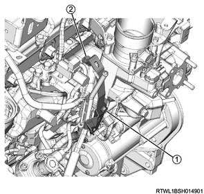
5) Final tighten the harness brackets to the inlet manifold in the order shown in the diagram.
Tightening torque: 10.0 N・m { 1.0 kgf・m / 89 lb・in }
5. Cylinder head cover installation
6. ECM setting
1. Injector ID Code programming
Note
- If the injector has been replaced, perform the Injector ID Code programming and ECM learned value clear.
1) Connect the scan tool to the DLC.
2) Turn ON the ignition switch.
3) Select the scan tool item.
- Diagnostics > Engine > 4JJ3 > Programming > Injector ID Code > Program Injector ID Code
4) Program the Injector ID Code into the ECM by following the on-screen instructions.
5) After the programming is completed, turn the ignition switch OFF for 30 seconds.
2. ECM learned value clear
1) Turn ON the ignition switch.
2) Select the scan tool item.
- Diagnostics > Engine > 4JJ3 > Special Function > Small Fuel Injection Quantity Clear
3) Perform the ECM learned value clear by following the on-screen instructions.
4) After the learned value clear is complete, turn OFF the ignition switch for 30 seconds.
3. Clear Learned Value (Fuel Mass Observer)
1) Turn ON the ignition switch.
Caution
- Do not start the engine.
2) Select the scan tool item.
- Diagnostics > Engine > 4JJ3 > Special Function > Clear Data > Clear Learned Value (Fuel Mass Observer)
3) Perform Clear Learned Value (Fuel Mass Observer) by following the on-screen instructions.
4) After Clear Learned Value (Fuel Mass Observer) is complete, turn OFF the ignition switch for 30 seconds.