1. Component views
Cylinder head cover
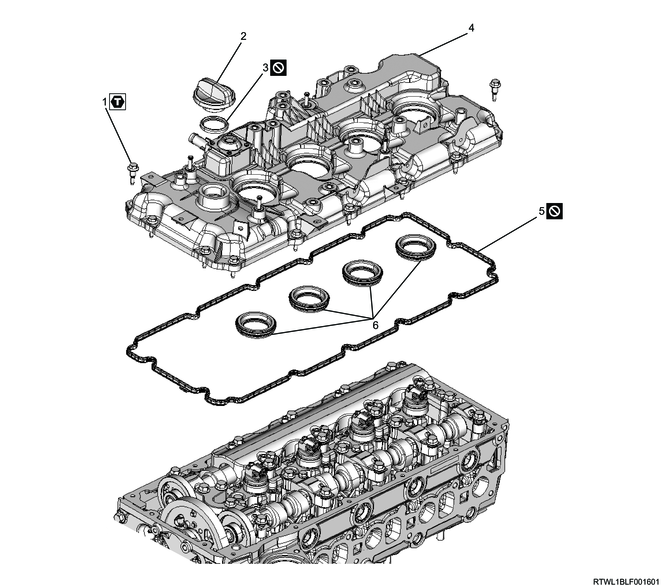
Part name
- Bolt
- Oil filler cap
- Oil filler cap gasket
- Cylinder head cover
- Cylinder head cover gasket
- Oil seal
Tightening torque
1-1: 5.0 N・m { 0.5 kgf・m / 44 lb・in }
1-2: 9.0 N・m { 0.9 kgf・m / 80 lb・in }
2. Cylinder head cover installation
1) Apply the engine oil to the oil seal.
2) Insert the oil seal from the lower side of the cylinder head cover until it reaches the far end.
3) Referring to the diagram, apply ThreeBond 1217H or 1207C to the cylinder head mating surface.
Caution
- Install the cylinder head cover within 5 minutes of applying liquid gasket.
- Remove any dirt or dust from the oil seal section on the injector connector side.
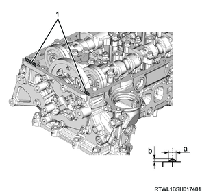
Legend
- Liquid gasket
Standard value
a: 2.0 to 2.5 mm { 0.079 to 0.098 in } Bead width
b: 1.0 to 1.5 mm { 0.039 to 0.059 in } Bead height
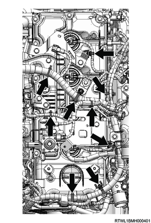
4) Temporarily tighten the cylinder head cover to the cylinder head in the order shown in the diagram.
Caution
- Do not reuse the gasket.
Tightening torque: 5.0 N・m { 0.5 kgf・m / 44 lb・in }
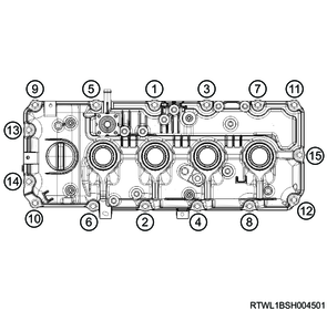
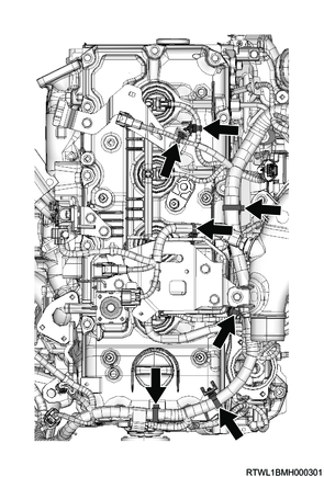
5) Final tighten the cylinder head cover to the cylinder head in the order shown in the diagram.
Tightening torque: 9.0 N・m { 0.9 kgf・m / 80 lb・in }
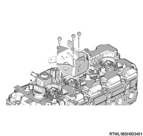
6) Install the harness bracket to the cylinder head cover.
Note
- For models with urethane covers, install together with the urethane cover.
- When installing the urethane cover, remove the oil filler cap before performing work.
Tightening torque: 25 N・m { 2.5 kgf・m / 18 lb・ft } Harness bracket
Models with urethane covers
Legend
- Filler cap
- Harness bracket
- Urethane cover
7) Connect the harness clip to the cylinder head cover.
RHD
LHD
8) Connect the PCV hose to the cylinder head cover.
3. Fuel leak-off hose installation
1) Install the injector leak-off pipe to the injector.
Caution
- Do not reuse the injector leak-off pipe or clip.
Legend
- Injector leak-off pipe
- Clip
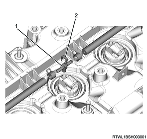
2) Install the fuel leak-off hose to the leak-off pipe.
3) Connect the connector to the injector.
Legend
- Fuel leak-off hose
- Injector connector
4. Air duct bracket installation
1) Install the air duct bracket to the cylinder head cover.
Tightening torque: 25 N・m { 2.5 kgf・m / 18 lb・ft }
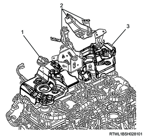
5. Differential pressure sensor bracket installation
1) Install the differential pressure sensor bracket to the cylinder head cover.
Tightening torque: 25 N・m { 2.5 kgf・m / 18 lb・ft }
2) Install the harness bracket to the cylinder head cover.
Tightening torque: 25 N・m { 2.5 kgf・m / 18 lb・ft }
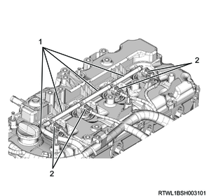
3) Connect the following sensor harnesses to the harness bracket.
- Exhaust gas temperature sensor 1 (Front of DPD filter)
- Exhaust gas temperature sensor 2 (Front of oxidation catalyst)
- Heated oxygen sensor
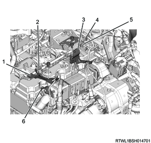
Legend
- Harness bracket
- Exhaust gas temperature sensor 1 (Front of DPD filter)
- Differential pressure sensor bracket
- Heated oxygen sensor
- Exhaust gas temperature sensor 2 (Front of oxidation catalyst)
- Harness bracket
6. Exhaust differential pressure sensor installation
7. Intake air duct installation
1) Install the intake duct to the intake throttle valve.
Tightening torque: 10.0 N・m { 1.0 kgf・m / 89 lb・in } Bolt
Tightening torque: 4.0 N・m { 0.4 kgf・m / 35 lb・in } Clamp (Intake throttle valve side)
2) Connect the air intake hose to the intercooler.
Caution
- Align the marks on the pipe side and hose side.
Tightening torque: 5.0 N・m { 0.5 kgf・m / 44 lb・in } Clamp (Intercooler side)

3) Connect the connector to charge air cooler temperature sensor 2.
8. Engine cover installation
1) Install the engine cover to the engine.

Legend
- Engine cover
9. Preliminary and post procedures
1. Post procedures
1) Connect the battery cable to the battery negative terminal.
2) Referring to the following, perform the setting of the front door power window switch with AUTO UP/AUTO DOWN function.
Refer to "9.Body, Cab, Accessories 9T.Glass, Windows, Mirrors front door power window switch setting".
3) Close the engine hood.