1. Component views
Cylinder block
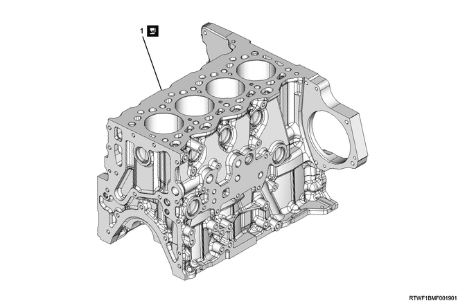
Part name
- Cylinder block
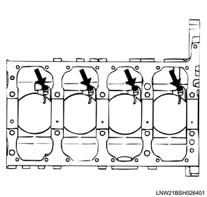
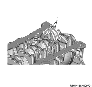
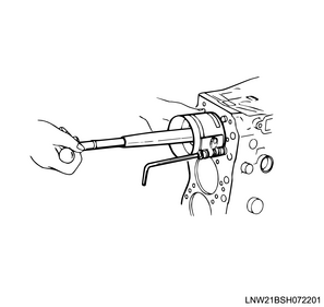
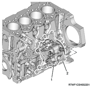
2. Piston oil jet installation
1) Install the oil jet pipe to the cylinder block.
Caution
- Do not damage or deform the oil jet pipe nozzle.
- After installing the crankshaft, piston, and connecting rod, rotate the crankshaft and make sure that there is no oil jet pipe interference.
Tightening torque: 20 N・m { 2.0 kgf・m / 14.8 lb・ft }
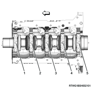
3. Crankshaft installation
If replacing the crankshaft bearing, select the crankshaft bearing grade.
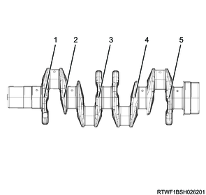
1) Check the cylinder block journal hole inner diameter grade.
Note
- Grade 1, 2, or 3 is marked on the bottom surface of the cylinder block.
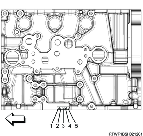
Legend
- No. 1
- No. 2
- No. 3
- No. 4
- No. 5
| Marking |
Journal diameter |
| 1 |
61.992 to 62.000 mm { 2.4406 to 2.4409 in } |
| 2 |
61.984 to 61.991 mm { 2.4403 to 2.4406 in } |
| 3 |
61.976 to 61.983 mm { 2.4400 to 2.4403 in } |
2) Check the crankshaft journal diameter grade.
Note
- The crankshaft journal grade marking is marked on each crankshaft journal.
Legend
- No. 1
- No. 2
- No. 3
- No. 4
- No. 5
| Marking |
Journal diameter |
|
| Other than the No. 3 journal |
No. 3 journal |
|
| 1 |
57.933 to 57.938 mm { 2.2808 to 2.2810 in } |
57.919 to 57.924 mm { 2.2803 to 2.2805 in } |
| 2 |
57.928 to 57.933 mm { 2.2806 to 2.2808 in } |
57.914 to 57.919 mm { 2.2801 to 2.2803 in } |
| 3 |
57.923 to 57.928 mm { 2.2804 to 2.2806 in } |
57.909 to 57.914 mm { 2.2799 to 2.2801 in } |
3) Inspect the crankshaft bearing for the following.
- Size
- Lot number
- Code
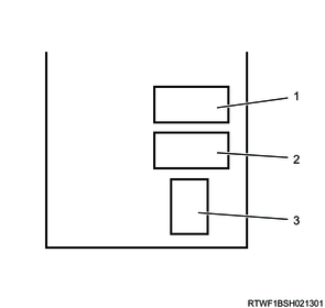
Legend
- Size
- Lot No.
- Code
4) Select the crankshaft bearing based on the journal hole inner diameter grades of the crankshaft journal and cylinder block.
| Crankshaft journal grade |
||||
| 1 |
2 |
3 |
||
| Cylinder block journal grade |
1 |
Code: 3 |
Code: 3 |
Code: 4 |
| 2 |
Code: 2 |
Code: 2 |
Code: 3 |
|
| 3 |
Code: 1 |
Code: 1 |
Code: 2 |
|
5) Install the crankshaft upper bearing to the cylinder block.
Note
- Check that the crankshaft upper bearing has oil holes and an oil groove.
Caution
- Do not confuse the difference of bearing shapes.
6) Apply engine oil to the crankshaft upper bearing surface.
Caution
- Do not apply engine oil to the cylinder block installation surface and back surface of the bearing.
7) Thoroughly apply engine oil to the crankshaft journal section.
8) Install the crankshaft to the cylinder block.
9) Thoroughly apply engine oil to the thrust bearing.
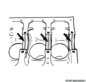
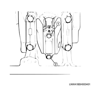
10) Install the thrust bearings to the front and rear sides of the cylinder block No. 4 journal.
Caution
- Install so that the oil groove of the thrust bearing touches the crankshaft.
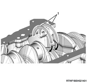
Legend
- Thrust bearing
11) Install the lower crankshaft bearing to the bearing cap.
12) Apply engine oil to the lower crankshaft bearing surface.
Caution
- Do not apply engine oil to the bearing cap installation surface and back surface of the bearing.
13) Install the thrust bearings to the front and rear sides of bearing cap No. 4.
Legend
- Thrust bearing
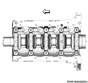
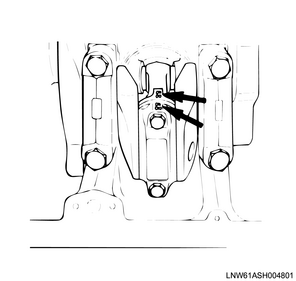
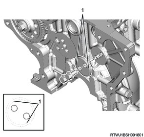
14) Install the bearing caps to the cylinder block in the order shown in the diagram.
Note
- Install so that the bearing cap front mark faces the front of the engine.
Legend
- No. 1
- No. 2
- No. 3
- No. 4
- No. 5
15) Apply engine oil to the threaded portions and seating surfaces of the bolts.
16) Tighten the bearing cap bolts to the cylinder block in the order shown in the diagram.
Caution
- Do not reuse the bearing cap bolt.
However, only when a new bearing cap bolt is used to measure the oil clearance, the bearing cap bolt can be reused.
Tightening torque: 50 N・m { 5.1 kgf・m / 36.9 lb・ft } 1st time
Tightening Angle : 60 to 90 ° 2nd time
17) Confirm that the crankshaft turns smoothly.
Caution
- After installing the piston and connecting rod, rotate the crankshaft and make sure that there is no interference with the oil jet.
4. Piston installation
1) Install the connecting rod bearing to the connecting rod.
2) Apply engine oil to the sliding surface of the connecting rod bearing.
Caution
- Do not apply engine oil to the connecting rod bearing installation surface and the back surface of the bearing.
3) Sufficiently apply the engine oil to the following locations.
- Piston ring
- Piston ring groove
- Piston side surface
- Cylinder bore surface
4) Turn the crankshaft in the forward direction and align to top dead center.
5) Install the piston to the cylinder block using the special tool.
Note
- Face the piston front mark towards the front.
- Use the piston ring compressor to insert the piston into the cylinder block.
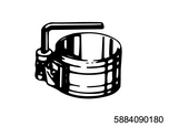
SST: 5-8840-9018-0 - piston setting tool
Caution
- When pushing the piston, do not allow the connecting rod to interfere with the oil jet.
- If the crank pin is at bottom dead center, the connecting rod may hit and damage the oil jet.
- Do not damage the cylinder block inner surface.
6) Install the connecting rod bearing to the bearing cap.
7) Apply engine oil to the sliding surface of the connecting rod bearing.
Caution
- Do not apply engine oil to the connecting rod bearing installation surface and the back surface of the bearing.
8) Apply engine oil to the threaded portions and seating surfaces of the bolts.
9) Temporarily tighten the bearing caps to the connecting rods after matching their cylinder numbers.
Caution
- Do not reuse the connecting rod bolts.
10) Final tighten the bearing cap bolts to the connecting rod in the order shown in the diagram, using a torque wrench and the special tool.
Tightening torque: 30 N・m { 3.1 kgf・m / 22 lb・ft } 1st time
Tightening Angle : 90 to 105 ° 2nd time
11) Turn the crankshaft and check that it turns smoothly without interference.
Caution
- Check that there is no oil jet deformation and that there is no interference with other parts.
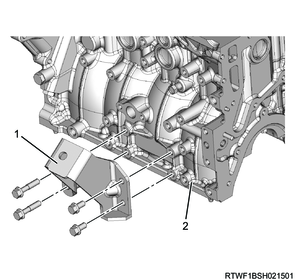
5. Engine foot installation
1) Install the left side engine foot to the cylinder block.
Tightening torque: 52 N・m { 5.3 kgf・m / 38 lb・ft }
Legend
- Left side engine foot
- Cylinder block
2) Install the right side engine foot to the cylinder block.
Tightening torque: 52 N・m { 5.3 kgf・m / 38 lb・ft }
Legend
- Right side engine foot
- Cylinder block
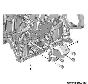
6. EGR cooler water pipe installation
1. Manual transmission models
1) Install EGR cooler water pipe B and EGR cooler water hose to the cylinder block.
Tightening torque: 25 N・m { 2.5 kgf・m / 18 lb・ft }
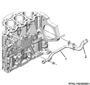
Legend
- EGR cooler water pipe B
- EGR cooler water hose
2. Automatic transmission models
1) Install EGR cooler water pipe B to the cylinder block.
Tightening torque: 25 N・m { 2.5 kgf・m / 18 lb・ft }
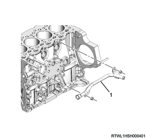
Legend
- EGR cooler water pipe B
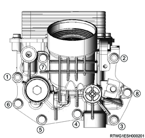
7. Oil filter installation
1) Install the oil filter and gasket to the cylinder block in the order shown in the diagram.
Caution
- Do not reuse the gasket.
Tightening torque: 25 N・m { 2.5 kgf・m / 18 lb・ft }
Tightening torque: 30 N・m { 3.1 kgf・m / 22 lb・ft } Spring clip
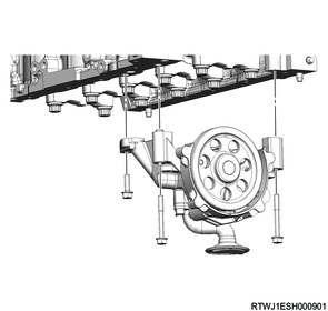
8. Fuel supply pump installation
1) Install the fuel supply pump and adapter to the cylinder block.
Tightening torque: 25 N・m { 2.5 kgf・m / 18 lb・ft }
Legend
- Fuel supply pump
- Adapter
2) Connect the fuel leak-off hose to the fuel supply pump.
3) Connect the fuel suction hose to the fuel supply pump.

Legend
- Fuel leak-off hose
- Fuel suction hose
4) Connect the connector to the FRP regulator.
5) Connect the connector to the fuel temperature sensor.

Legend
- FRP regulator connector
- Fuel temperature sensor connector
9. Idle gear installation
1) Apply engine oil to the threaded portions and the bearing surfaces of the bolts.
2) Install the flange to the cylinder block with the front mark facing toward the front.
Tightening torque: 32 N・m { 3.3 kgf・m / 24 lb・ft }
Legend
- Front mark
3) Apply engine oil to the idle gear A shaft.
4) Install the idle gear A shaft to the cylinder block by aligning the cylinder block and idle gear A shaft oil holes.
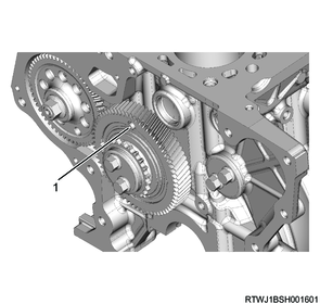
5) Install idle gear A to the idle gear A shaft by aligning the mark on idle gear A.
Crank gear side alignment mark
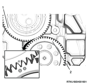
Legend
- Idle gear A
- Crank gear
Supply pump gear side alignment mark
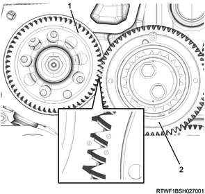
Legend
- Supply pump gear
- Idle gear A
6) Install the flange to idle gear A with the front mark facing toward the front.
7) Apply engine oil to the threaded portions and seating surfaces of the idle gear A bolts.
8) Temporarily tighten idle gear A to the idle gear A shaft and cylinder block.

Legend
- Front mark
9) Final tighten idle gear A to the cylinder block.
Tightening torque: 32 N・m { 3.3 kgf・m / 24 lb・ft }
10) Remove the M5 bolts for securing the sub gear from idle gear A.
Legend
- M5 bolt
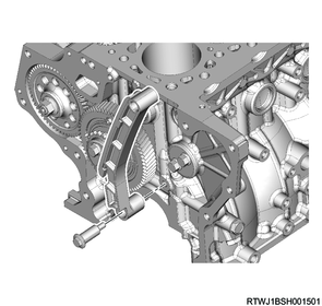
11) Install the timing chain guide to the cylinder block.
Tightening torque: 25 N・m { 2.5 kgf・m / 18 lb・ft }
10. Oil pump installation
1) Install the oil pump to the cylinder block.
Tightening torque: 25 N・m { 2.5 kgf・m / 18 lb・ft }