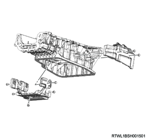
1. Engine removal
2. Catalytic converter removal
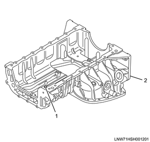
3. Engine oil drain
1) Remove the drain plug from the oil pan, and drain the engine oil to a pan.
2) Install the drain plug to the oil pan.
Tightening torque: 44 N・m { 4.5 kgf・m / 32 lb・ft }
Caution
- Do not reuse the gasket.
- Do not forget to tighten the drain plug.
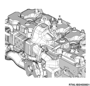
4. EGR cooler water hose disconnect
1) Disconnect the EGR cooler water feed hose from the EGR cooler.
2) Disconnect the EGR cooler water return hose from the EGR cooler.

Legend
- EGR cooler water return hose
- EGR cooler water feed hose
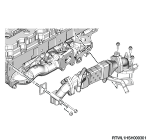
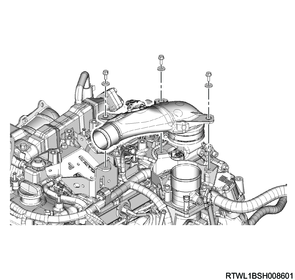
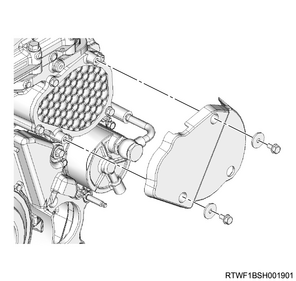
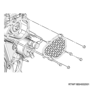
5. EGR cooler removal
1) Remove the upper heat protector from the EGR duct.
2) Remove the lower heat protector from the EGR duct.

3) Remove the EGR cooler and gasket from the cylinder head and exhaust manifold.
Caution
- Do not reuse the gasket.
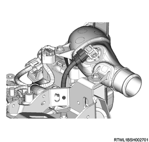
6. Turbocharger water hose disconnect
1) Disconnect the turbocharger water feed hose from the water feed and return pipe.
2) Disconnect the turbocharger water return hose from the water feed and return pipe.

Legend
- Turbocharger water feed hose
- Turbocharger water return hose
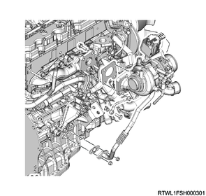
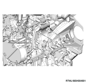
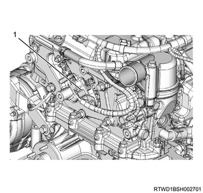
7. Turbocharger oil pipe disconnect
1) Disconnect the turbocharger oil pipe from the oil cooler and crankcase.
Caution
- To prevent the intrusion of foreign material, seal the connections.
- Do not reuse the gasket.

Legend
- Turbocharger oil pipe
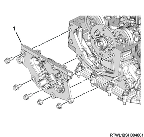
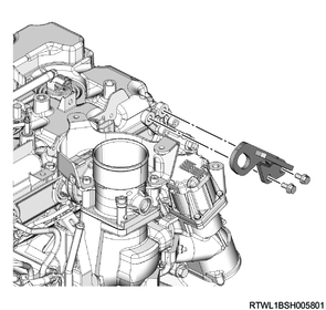
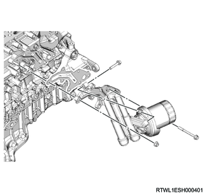
8. Turbocharger bracket removal
1) Remove the turbocharger bracket from the cylinder block.

Legend
- Turbocharger bracket
9. Turbocharger removal
1) Disconnect the connector from the turbocharger.
2) Remove the following parts as a set from the exhaust manifold.
- Turbocharger
- Turbocharger oil pipe
- Water feed and return pipe
Caution
- To prevent the intrusion of foreign material, seal the connections.
- Do not reuse the gasket.
10. Intake air duct removal
1) Disconnect the connector from the boost pressure sensor.
2) Remove the intake air duct from the intake throttle valve.
11. Intake throttle valve removal
1) Disconnect the connector from the intake throttle valve.
2) Remove the following parts from the inlet manifold.
- Air duct bracket
- Intake throttle valve
- Gasket
Caution
- Do not reuse the gasket.
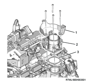
Legend
- Air duct bracket
- Intake throttle valve
- Gasket
12. Air duct bracket removal
1) Remove the air duct bracket from the cylinder head cover.
13. Fuel leak-off hose removal
1) Disconnect the connector from the injector.
2) Remove the fuel leak-off hose from the leak-off pipe.
Legend
- Fuel leak-off hose
- Injector connector
3) Remove the injector leak-off pipe from the injector.
Caution
- Do not reuse the injector leak-off pipe or clip.
Legend
- Injector leak-off pipe
- Clip
14. Cylinder head cover removal
1) Disconnect the PCV hose from the cylinder head cover.
2) Disconnect the harness clip from the cylinder head cover.
RHD
LHD
3) Remove the harness bracket from the cylinder head cover.
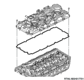
4) Remove the cylinder head cover from the cylinder head.
Caution
- Do not reuse the gasket.
5) Remove the oil seal from the lower side of the cylinder head cover.
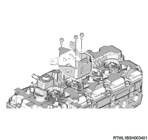
15. A/C compressor bracket removal
1) Remove the A/C compressor bracket from the cylinder head.
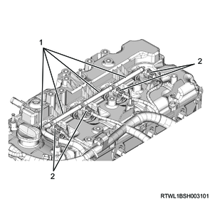
16. Leak-off pipe removal
1) Remove the harness bracket from the inlet manifold.

Legend
- Harness bracket
2) Disconnect the 3 vacuum hoses from the vacuum pipe.
3) Disconnect the 2 leak-off hoses from the leak-off pipe.
4) Remove the leak-off pipe from the inlet manifold.
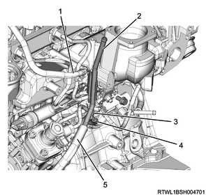
Legend
- Leak-off hose (Injector side)
- Leak-off pipe
- Leak-off hose (Supply pump side)
- Vacuum hose (Swirl control valve side)
- Vacuum hose (Vacuum pump side)
17. Swirl control solenoid valve removal
1) Disconnect the connector from the swirl control solenoid valve.
2) Disconnect the vacuum hose from swirl control solenoid valve.
3) Remove the swirl control solenoid valve and bracket as a set from the inlet manifold.
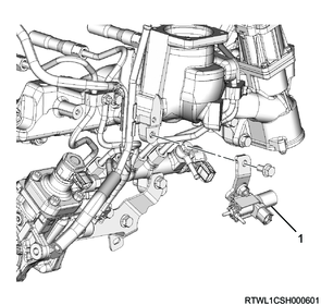
Legend
- Swirl control solenoid valve
18. Injection pipe removal
1) Remove the clip from the injection pipe.
2) Remove the injection pipes from the injector and common rail (fuel rail).
Caution
- Do not reuse the injection pipe.
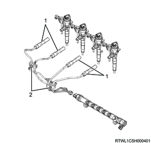
Legend
- Injection pipe
- Clip
19. Injector removal
1) Remove the injector clamp from the injector.
2) Remove the injector from the cylinder head.
Note
- If it is difficult to remove the injector, use a remover.
- Store the removed injectors with the cylinder numbers attached.
Caution
- Cover the exposed portion to prevent foreign material from getting into the fuel system.
- Do not damage the injector nozzle.
- Absolutely never touch the injector solenoids because that can hinder their performance or cause damage.
3) Remove the gasket from the injector.
4) Remove the O-ring from the injector.
Caution
- Do not reuse the following parts.
- Clip
- O-ring
- Gasket

Legend
- Injector
- Leak-off pipe
- Clip
- O-ring
- Gasket
20. Tension pulley removal
1) Remove the tension pulley from the cylinder head.
21. Water pipe removal
1) Remove the water pipe from the following parts.
- Thermostat
- Cylinder head
- Turbocharger
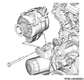
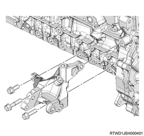
22. Generator removal
1) Disconnect the B-terminal from the generator.
2) Disconnect the connector from the generator.
3) Remove the upper bracket from the generator and timing gear case.
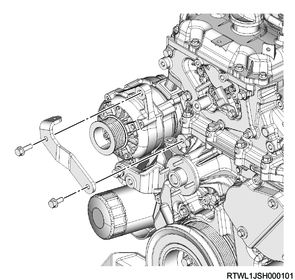
4) Remove the generator from the lower bracket.
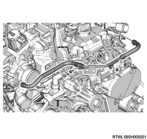
23. EGR water pipe removal
1) Disconnect the water hose from the water intake pipe and return hose.
2) Install the EGR water pipe to the oil cooler and turbocharger lower bracket.

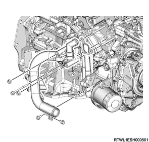
24. Water intake pipe removal
1) Remove the water intake pipe and water hose as a set from the oil filter and oil cooler.
Caution
- Do not reuse the gasket.
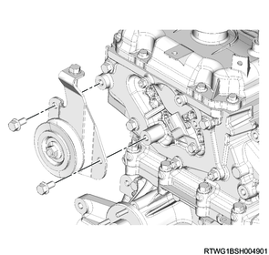
25. Tension pulley removal
1) Remove the tension pulley from the generator bracket.
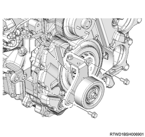
2) Remove the generator lower bracket from the cylinder block and timing gear case.
26. Glow plug removal
1) Remove the glow plug terminal and glow plug connector from the glow plug.

Legend
- Glow plug terminal
- Glow plug connector
2) Remove the glow plug from the cylinder head.

Legend
- Glow plug
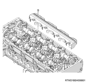
27. Baffle plate removal
1) Rotate the crankshaft in the forward direction (clockwise) to align the No. 1 cylinder piston to compression top dead center.

Legend
- Alignment mark of No. 1 cylinder compression top dead center
2) Remove the baffle plate from the cylinder head.
28. Timing chain upper cover removal
1) Disconnect the connector from the CMP sensor.
Legend
- CMP sensor
2) Remove the timing chain upper cover from the cylinder head.
Legend
- Timing chain upper cover
29. Timing chain lower cover removal
1) Remove the noise cover from the timing chain lower cover.
2) Remove the timing chain lower cover from the gear case cover.
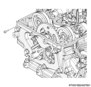
30. Timing chain removal
1) Rotate the crankshaft in the forward direction (clockwise) to align the No. 1 cylinder piston to compression top dead center.
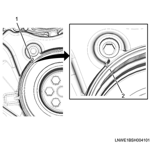
Legend
- Top dead center alignment mark on the gear case cover side
- Crankshaft pulley side top dead center alignment mark
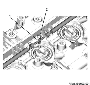
2) Align the marks of the camshaft upper bracket and camshaft.
Legend
- Alignment mark
3) Remove the oil feed pipe from the timing chain tensioner.
Caution
- Do not reuse the gasket.
4) Remove the timing chain tensioner and gasket from the cylinder head.
Caution
- Do not reuse the gasket.
Legend
- Oil feed pipe
- Timing chain tensioner
- Gasket
5) Remove the timing chain lever pivot from the timing chain tension lever.
6) Remove the idle gear D shaft bolt and sleeve from idle gear D and sprocket.
7) Remove the timing chain and sprocket as a set from idle gear D.
Legend
- Idle gear D shaft bolt
- Sleeve
- Sprocket
8) Remove the timing chain from the supply pump sprocket by lowering the timing chain and sprocket.
9) Take the timing chain tension lever out from the cylinder head.
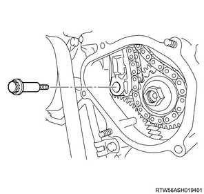
10) Remove the timing chain guide from the cylinder head and cylinder block.
Legend
- Timing chain guide bolt
31. Camshaftbracket removal
1) Use the M5 lock bolt to secure the camshaft gear.
2) Remove the following parts as a set from the cylinder head.
- Camshaft bracket
- Rocker arm shaft
- Camshaft
- Idle gear D
Legend
- Camshaft bracket
- Cylinder head
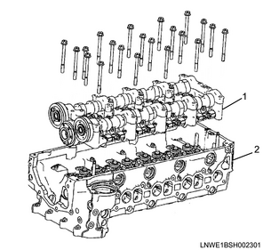
32. Cylinder head removal
1) Install special tool to the cylinder head.
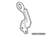
SST: 5-8840-2886-0 - rear engine hanger
Tightening torque: 25 N・m { 2.5 kgf・m / 18 lb・ft }
2) Install the wire to the engine hanger and hoist.
3) Remove the nuts and bolts from between cylinder head and timing gear case.
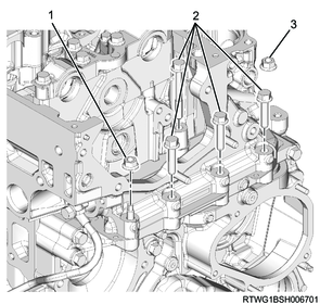
Legend
- Nut
- Bolt
- Nut
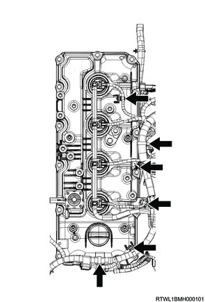
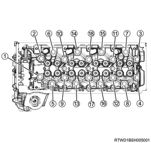
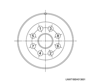
4) Loosen the cylinder head bolts in the order shown in the diagram.
Caution
- Do not reuse the cylinder head bolts.
5) Remove the cylinder head from the cylinder block.
6) Remove the cylinder head gasket and timing gear case gasket from the cylinder head.
Caution
- Do not reuse the cylinder head gasket and timing gear case gasket.
33. Fuel feed pipe removal
1) Remove the fuel feed pipe from the fuel supply pump and common rail (fuel rail).
Caution
- Do not reuse the fuel feed pipe.
- Cover the exposed section to prevent the intrusion of foreign material.
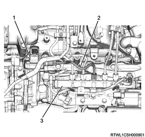
Legend
- Fuel supply pump
- Fuel feed pipe
- Common rail (fuel rail)
34. Fuel leak-off pipe removal
1) Remove the fuel leak-off pipe from the fuel supply pump and common rail (fuel rail).
Caution
- Cover the exposed section to prevent the intrusion of foreign material.
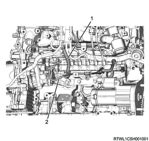
Legend
- Leak-off hose
- Fuel leak-off pipe
35. Common rail (fuel rail) removal
1) Disconnect the connector from the FRP sensor.
Note
- Disconnect it between the engine harness and the sub-harness.
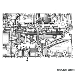
Legend
- Common rail (fuel rail)
- FRP sensor connector
2) Remove the common rail (fuel rail) from the cylinder block.
Caution
- Do not hold the FRP sensor or pressure-reducing valve.
- Do not damage the FRP sensor or pressure-reducing valve.

Legend
- FRP sensor
- Common rail (fuel rail)
- Pressure-reducing valve
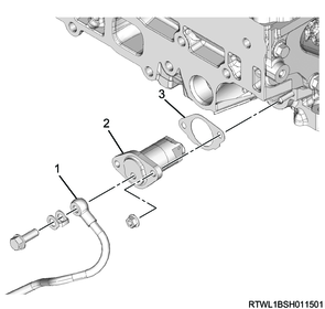
36. Vacuum pump removal
1) Remove the vacuum pipe as a set with the vacuum hose from the timing gear case and vacuum pump.
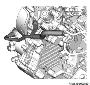
2) Remove the vacuum pump oil pipe from the vacuum pump and cylinder block.
3) Remove the vacuum pump from the gear case cover.
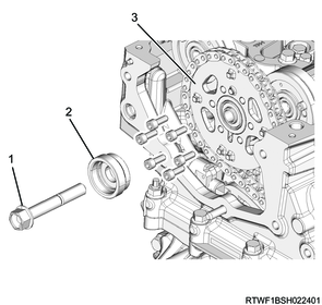
37. Crankshaft pulley removal
1) Install the special tool to the starter installation section of the rear plate.
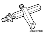
SST: 5-8840-0214-0 - crankshaft stopper
2) Remove the crankshaft pulley from the crankshaft.
Caution
- Do not reuse the crankshaft pulley bolt and washer.
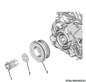
Legend
- Bolt
- Washer
- Crankshaft pulley
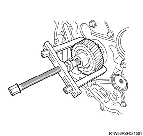
38. Crankshaft front oil seal removal
1) Remove the cover from the gear case cover.
2) Install the crankshaft pulley bolt and 17 mm {0.67 in} collar or equivalent to the crankshaft to secure the crank gear.
Note
- When removing the slinger, take care to prevent the crank gear from falling out.
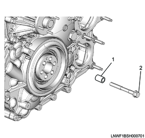
Legend
- 17 mm {0.67 in} collar or equivalent
- Crankshaft pulley bolt
3) Remove the crankshaft front oil seal and slinger as a set from the crankshaft using the special tool.
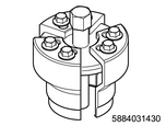
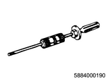
SST: 5-8840-3143-0 - slinger puller
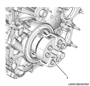
Legend
- 5-8840-3143-0
Caution
- Do not reuse the crankshaft front oil seal.
- Do not forget to take out the installed bolts.
- Do not damage the oil seal installation section of the crankshaft gear or timing gear case cover.
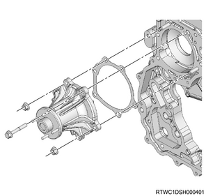
39. Water pump removal
1) Remove the water pump and gasket from the timing gear case.
Caution
- Do not reuse the gasket.
40. Oil filter removal
1) Remove the oil filter and gasket from the oil cooler.
Caution
- Do not reuse the gasket.
41. Gear case cover removal
1) Remove the gear case cover from the timing gear case.
Caution
- Do not reuse the gasket.
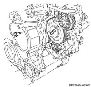
42. Supply pump gear removal
1) Apply the dial gauge to the idle gear tooth to be measured, and gently move the gear left and right to measure the fluctuation of the dial gauge.
Note
- Replace the idle gear if the measured value exceeds the standard value.
Standard: 0.10 to 0.17 mm { 0.0039 to 0.0067 in }
Limit: 0.30 mm { 0.0118 in }
2) Measure the idle gear axial direction clearance using a feeler gauge.
Note
- Replace the idle gear or thrust collar if the measured value exceeds the limit.
| Idle gear |
Standard value |
Limit |
| A |
0.055 to 0.130 mm { 0.0022 to 0.0051 in } |
0.20 mm { 0.0079 in } |
| C |
0.055 to 0.130 mm { 0.0022 to 0.0051 in } |
|
| D |
0.090 to 0.155 mm { 0.0035 to 0.0061 in } |
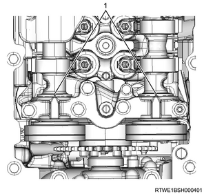
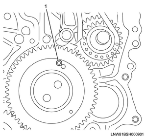
3) Turn the crankshaft in the forward direction (clockwise) to align the marks with idle gear A and the supply pump gear removal or installation position.
Note
- Referring to the diagram, align the three-dot marks.

Legend
- Supply pump installation or removal position
- TDC position
4) Install the M6 bolt for securing the sub gear to idle gear A.
Legend
- M6 bolt
43. Idle gear removal
1) Remove the flange from idle gear A.
2) Remove idle gear A from the idle gear A shaft.
3) Remove the idle gear A shaft from the timing gear case.
4) Remove idle gear C from the idle gear C shaft.
5) Remove the idle gear C shaft from the timing gear case.

6) Remove the crank gear from the crankshaft.
7) Remove idle gear D from the idle gear shaft.
8) Remove the idle gear D shaft from the camshaft brackets.
Legend
- Idle gear D
- Idle gear D shaft
- Camshaft bracket
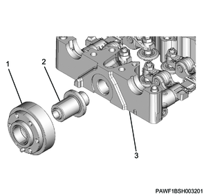
44. Fuel supply pump removal
1) Disconnect the connector from the fuel supply pump.
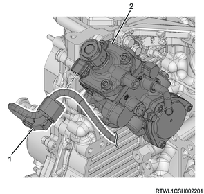
Legend
- Fuel supply pump connector
- Fuel supply pump
2) Remove the fuel supply pump from the timing gear case.
3) Remove the O-ring from the fuel supply pump.
Caution
- Do not reuse the O-ring.
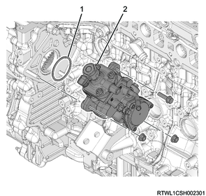
Legend
- O-ring
- Fuel supply pump
45. Oil pump removal
1) Remove the oil pump from the timing gear case.
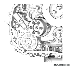
Legend
- Oil pump
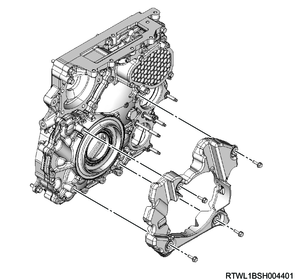
46. Timing gear case removal
1) Remove the timing gear case bracket from the timing gear case and cylinder block.
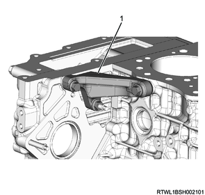
Legend
- Timing gear case bracket
2) Remove the timing gear case and gasket from the cylinder block.
Caution
- Do not reuse the gasket.
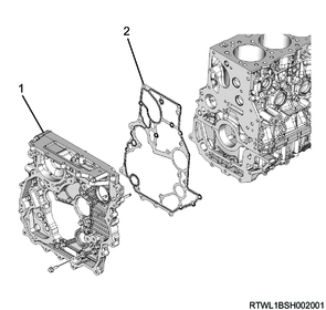
Legend
- Timing gear case
- Gasket
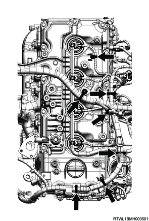
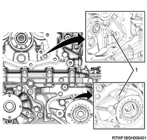
Caution
- Do not remove the bolts indicated by the arrows in the diagram when removing or installing the timing gear case.
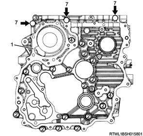
Legend
- Timing gear case
- Bolt L = 25 mm {0.98 in}
- Bolt L = 60 mm {2.36 in}
- Bolt L = 45 mm {1.77 in}
- Bolt L = 35 mm {1.38 in}
- Bolt L = 16 mm {0.63 in}
- Bolt not to be removed
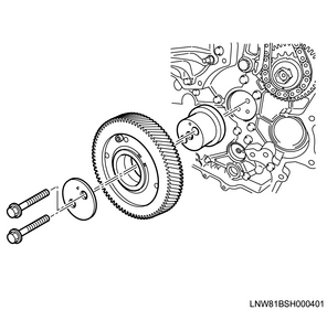
47. Flywheel removal
1. Manual transmission models
1) Remove the pilot bearing from the flywheel using the special tool.
SST: 5-8840-2000-0 - Pilot bearing remover
SST: 5-8840-0019-0 - Sliding hammer

2) Install the special tool to the starter installation section of the rear plate.
SST: 5-8840-0214-0 - crankshaft stopper
3) Gradually loosen the flywheel mounting bolts in the order shown in the diagram, and remove the washer and flywheel from the crankshaft.
4) After loosening all of the bolts, remove the special tool and then remove the flywheel.
2. Automatic transmission models
1) Install the special tool to the starter installation section of the rear plate.
SST: 5-8840-0214-0 - crankshaft stopper
2) Gradually loosen the flywheel mounting bolts in the order shown in the diagram.
3) Remove the following parts from the crankshaft.
- Washer
- Flexible plate
- Flywheel
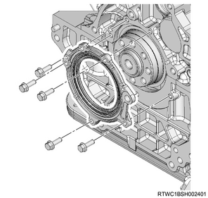
48. Oil seal retainer removal
1) Remove the oil seal retainer and crankshaft rear oil seal as a set from the cylinder block and crankcase.
Caution
- Do not reuse the crankshaft rear oil seal.
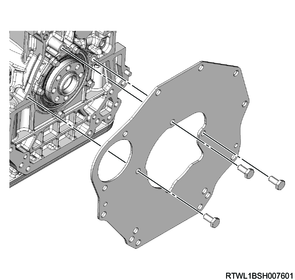
49. Rear plate removal
1) Remove the rear plate from the cylinder block and crankcase.
50. Crankshaft rear oil seal removal
1) Remove the crankshaft rear oil seal from the oil seal retainer.
Caution
- Do not reuse the crankshaft rear oil seal.
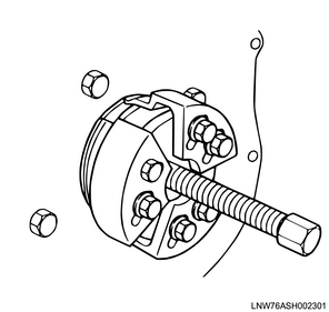
2) Remove the crankshaft rear slinger from the crankshaft using the special tool.
Note
- Referring to the diagram, install the slinger puller and remove the slinger.
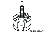
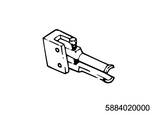
SST: 5-8840-2360-0 - rear oil seal remover
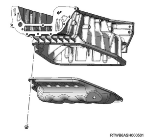
51. Oil pan removal
1) Remove the oil pan from the crankcase.
52. Crankcase removal
1) Remove the crankcase cover from the crankcase.
2) Remove the crankcase from the cylinder block.
3) Remove the O-ring from the crankcase.
Caution
- Do not reuse the O-ring.
Legend
- O-ring
- Crankcase