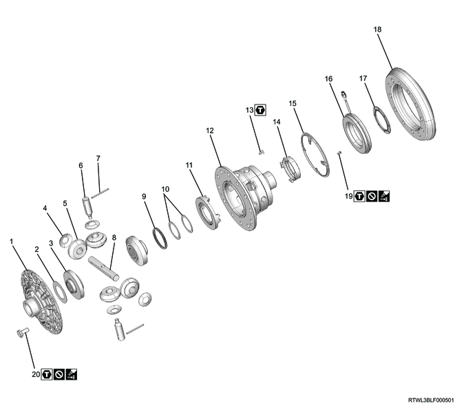
1. Component views
Rear differential cage (φ220 mm {8.66 in}) (Differential lock)
Part name
- Differential cage A
- Thrust washer
- Side gear
- Pinion washer
- Pinion gear
- Pinion shaft S
- Lock pin
- Pinion shaft L
- Return spring
- Thrust washer
- Cam ring
- Differential cage B
- Screw bolt
- Plunger
- Position plate
- Coil assembly
- Solenoid washer
- Ring gear
- Bolt
- Bolt
Tightening torque
13: 4.5 N・m { 0.5 kgf・m / 40 lb・in }
19: 6.9 N・m { 0.7 kgf・m / 61 lb・in }
20: 145 N・m { 14.8 kgf・m / 107 lb・ft }
2. Final drive safety information
When assembling, if nothing in particular is specified, refer to the following and apply or add differential oil.
Refer to "201.General Information 14B.Vehicle Information recommended fluids, lubricants and diesel fuels".
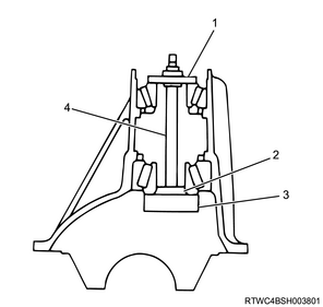
3. Differential cage reassembly
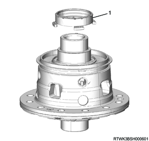
1) Install the cam ring to differential cage B.
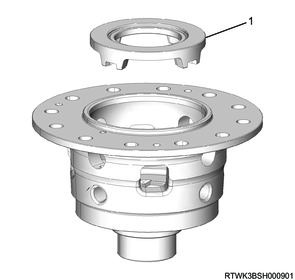
Legend
- Cam ring
2) Install the return spring and thrust washer to the cam ring.
3) Install the following parts to differential cage B.
Note
- Install a longer pinion shaft first.
- Pinion washer
- Pinion gear
- Pinion shaft
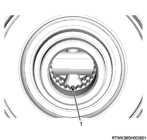
4) Install the lock pin to differential cage B.
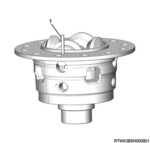
Legend
- Lock pin
5) Install the side gear and thrust washer to differential cage B.
6) Install differential cage A to differential cage B.
Note
- Install the differential cage based on the alignment marks that were made during removal.
Tightening torque: 4.5 N・m { 0.5 kgf・m / 40 lb・in }
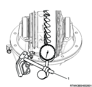
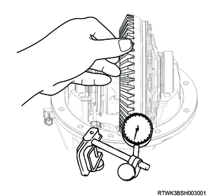
7) Measure the clearance in the thrust direction between the side gear and the differential cage using a dial gauge.
Note
- If the clearance in the thrust direction between the side gear and the differential cage is outside the standard range, change the thrust washer thickness and adjust.
- By adjusting the clearance in the thrust direction between the side gear and the differential cage, the backlash between the side gears is adjusted.
Caution
- Check that the side gear rotates smoothly.
Standard: 0.20 mm or less { 0.008 in or less }
| Side gear |
Thrust washer |
Thickness |
| Side gear |
Thrust washer (No.1) |
1.05 to 1.15 mm { 0.041 to 0.045 in } |
| 1.15 to 1.25 mm { 0.045 to 0.049 in } |
||
| 1.25 to 1.35 mm { 0.049 to 0.053 in } |
||
| 1.35 to 1.45 mm { 0.053 to 0.057 in } |
||
| Side gear (Dog clutch side) |
Thrust washer (No.2) |
1.05 to 1.15 mm { 0.041 to 0.045 in } |
| 1.15 to 1.25 mm { 0.045 to 0.049 in } |
||
| 1.25 to 1.35 mm { 0.049 to 0.053 in } |
||
| 1.35 to 1.45 mm { 0.053 to 0.057 in } |
||
| Thrust washer (No.3) |
1.35 to 1.45 mm { 0.053 to 0.057 in } |

Legend
- Measurement point
8) Install the position plate to the differential cage.
Caution
- Do not reuse the bolt.
This is because locking agent is applied to the threaded portion.
Tightening torque: 6.9 N・m { 0.7 kgf・m / 61 lb・in }
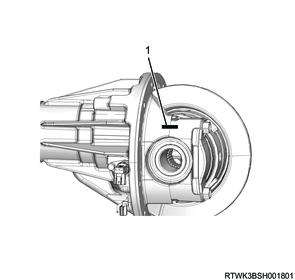
9) Install the plunger to the differential cage.
Legend
- Plunger
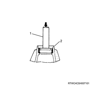
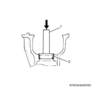
10) Install the coil assembly and solenoid washer using the special tool.
Caution
- Do not allow the solenoid washer to protrude from the differential case end surface.
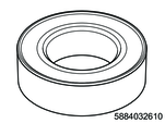
SST: 5-8840-3261-0 - solenoid washer installer
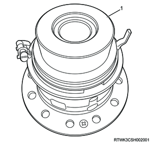
Legend
- 5-8840-3261-0
Standard: 0.00 to 0.15 mm { 0.000 to 0.006 in } From the differential case end surface
11) Apply LOCTITE 263 to the threaded portion of the bolts and the ring gear threaded holes.
12) Install the ring gear to the differential cage.
Note
- Apply LOCTITE 263 to the threaded portion of the bolts from the end toward the center in a straight line.
Caution
- If using any adhesive other than LOCTITE 263, the bolts may be loosened or broken.
- Do not reuse the bolts, when replacing the ring gear.
- Replace the ring gear and drive pinion as a set.
Ring gear bolt tightening order
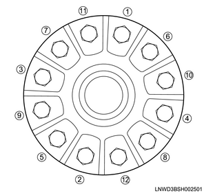
Tightening torque: 145 N・m { 14.8 kgf・m / 107 lb・ft }
4. Final drive reassembly
1) Install the outer bearing outer race to the differential carrier using the special tool.
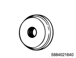
SST: 5-8840-2164-0 - bearing installer
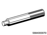
SST: 5-8840-0007-0 - grip
Legend
- 5-8840-0007-0
- 5-8840-2164-0
2) Install the inner bearing outer race to the differential carrier using the special tool.

SST: 5-8840-2163-0 - bearing installer
SST: 5-8840-0007-0 - grip
Legend
- 5-8840-0007-0
- 5-8840-2163-0
3) Apply differential oil to the inner bearing inner race and outer bearing inner race.
4) Install the following parts to the differential carrier.
- Inner bearing inner race
- Outer bearing inner race
- Special tool
Caution
- Thoroughly clean the special tool before using it.
SST: 5-8840-2166-0 - gauge plate
SST: 5-8840-0129-0 - pilot
SST: 5-8840-0127-0 - stud & nut
SST: 5-8840-2085-0 - pilot
Tightening torque: 2.7 N・m { 0.3 kgf・m / 24 lb・in } Special tool nut
Legend
- 5-8840-0129-0
- 5-8840-2085-0
- 5-8840-2166-0
- 5-8840-0127-0
5) Clean the side bearing installation section.
6) Install the special tool and dial indicator to the differential carrier.
SST: 5-8840-0126-0 - dial indicator
SST: 5-8840-2166-0 - gauge plate
SST: 5-8840-2167-0 - disc 2pcs.required
SST: 5-8840-0128-0 - arbor
7) Install the bearing cap to the differential carrier.
Tightening torque: 108 N・m { 11.0 kgf・m / 80 lb・ft }

Legend
- 5-8840-0126-0
- 5-8840-2166-0
- 5-8840-2167-0
- 5-8840-0128-0
Note
- The dial indicator scale display is in inches.
8) Set the dial indicator scale to 0.
9) Bring the dial indicator into contact with the arbor plunger section, then push the dial indicator down to the point where the needle rotates approximately halfway in the clockwise direction, and secure.
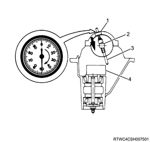
Legend
- 5-8840-0126-0
- 5-8840-0128-0
- Plunger (5-8840-0128-0)
- 5-8840-2166-0
10) Set the dial indicator scale to 0.
11) Place the end of the arbor plunger on top of the gauge plate.
12) Move the arbor back and forth, and verify the position where the dial indicator runout is largest.
13) Set the dial indicator scale to 0 at the position where the dial indicator runout is largest.
Note
- Perform the above procedure again to confirm the 0 point.
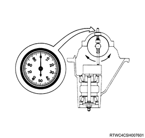
14) Rotate the arbor and move the end of the plunger away from the gauge plate.
15) Record the value indicated on the dial indicator.
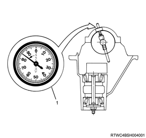
Legend
- Example: when the dial indicator reading numerical value is 0.085
16) Record the pinion depth code on the drive pinion upper section.
If the value is positive, the mesh depth is too large, so decrease the shim thickness.
If the value is negative, the mesh depth is too small, so increase the shim thickness.
0 indicates that no adjustment is required.
Ex: If the value is +2, the mesh depth is 0.02 mm {0.0008 in} too large, so decrease the shim thickness by 0.02 mm {0.0008 in}.
If the value is negative, perform the opposite.

17) Select the appropriate adjust shim based on the value read by the dial indicator and the drive pinion code.
Note
- Select a shim from the following table.
| Dial indicator reading (in) |
Drive pinion depth code |
|||||
| 10 |
8 |
6 |
4 |
2 |
0 |
|
| 0.073 |
||||||
| 0.074 |
||||||
| 0.075 |
||||||
| 0.076 |
1.94 {0.0764} |
|||||
| 0.077 |
1.96 {0.0772} |
|||||
| 0.078 |
1.94 {0.0764} |
1.96 {0.0772} |
1.98 {0.0780} |
|||
| 0.079 |
1.94 {0.0764} |
1.96 {0.0772} |
1.98 {0.0780} |
2.00 {0.0787} |
||
| 0.080 |
1.94 {0.0764} |
1.96 {0.0772} |
1.98 {0.0780} |
2.00 {0.0787} |
2.02 {0.0795} |
2.04 {0.0803} |
| 0.081 |
1.96 {0.0772} |
1.98 {0.0780} |
2.00 {0.0787} |
2.02 {0.0795} |
2.04 {0.0803} |
2.06 {0.0811} |
| 0.082 |
1.98 {0.0780} |
2.00 {0.0787} |
2.02 {0.0795} |
2.04 {0.0803} |
2.06 {0.0811} |
2.08 {0.0819} |
| 0.083 |
2.00 {0.0787} |
2.02 {0.0795} |
2.04 {0.0803} |
2.06 {0.0811} |
2.08 {0.0819} |
2.10 {0.0827} |
| 0.084 |
2.04 {0.0803} |
2.06 {0.0811} |
2.08 {0.0819} |
2.10 {0.0827} |
2.12 {0.0835} |
2.14 {0.0843} |
| 0.085 |
2.06 {0.0811} |
2.08 {0.0819} |
2.10 {0.0827} |
2.12 {0.0835} |
2.14 {0.0843} |
2.16 {0.0850} |
| 0.086 |
2.08 {0.0819} |
2.10 {0.0827} |
2.12 {0.0835} |
2.14 {0.0843} |
2.16 {0.0850} |
2.18 {0.0858} |
| 0.087 |
2.12 {0.0835} |
2.14 {0.0843} |
2.16 {0.0850} |
2.18 {0.0858} |
2.20 {0.0866} |
2.22 {0.0874} |
| 0.088 |
2.14 {0.0843} |
2.16 {0.0850} |
2.18 {0.0858} |
2.20 {0.0866} |
2.22 {0.0874} |
2.24 {0.0882} |
| 0.089 |
2.16 {0.0850} |
2.18 {0.0858} |
2.20 {0.0866} |
2.22 {0.0874} |
2.24 {0.0882} |
2.26 {0.0890} |
| 0.090 |
2.18 {0.0858} |
2.20 {0.0866} |
2.22 {0.0874} |
2.24 {0.0882} |
2.26 {0.0890} |
2.28 {0.0898} |
| 0.091 |
2.20 {0.0866} |
2.24 {0.0882} |
2.26 {0.0890} |
2.28 {0.0898} |
2.30 {0.0906} |
2.32 {0.0913} |
| 0.092 |
2.24 {0.0882} |
2.26 {0.0890} |
2.28 {0.0898} |
2.30 {0.0906} |
2.32 {0.0913} |
2.34 {0.0921} |
| 0.093 |
2.26 {0.0890} |
2.28 {0.0898} |
2.30 {0.0906} |
2.32 {0.0913} |
2.34 {0.0921} |
2.36 {0.0929} |
| 0.094 |
2.28 {0.0898} |
2.30 {0.0906} |
2.32 {0.0913} |
2.34 {0.0921} |
2.36 {0.0929} |
|
| 0.095 |
2.32 {0.0913} |
2.34 {0.0921} |
2.36 {0.0929} |
|||
| 0.096 |
2.34 {0.0921} |
2.36 {0.0929} |
||||
| 0.097 |
2.36 {0.0929} |
|||||
| Dial indicator reading (in) |
Drive pinion depth code |
|||||
| 0 |
-2 |
-4 |
-6 |
-8 |
-10 |
|
| 0.073 |
1.94 {0.0764} |
1.96 {0.0772} |
||||
| 0.074 |
1.94 {0.0764} |
1.96 {0.0772} |
1.98 {0.0780} |
|||
| 0.075 |
1.94 {0.0764} |
1.96 {0.0772} |
1.98 {0.0780} |
2.00 {0.0787} |
||
| 0.076 |
1.94 {0.0764} |
1.96 {0.0772} |
1.98 {0.0780} |
2.00 {0.0787} |
2.02 {0.0795} |
2.04 {0.0803} |
| 0.077 |
1.96 {0.0772} |
1.98 {0.0780} |
2.00 {0.0787} |
2.02 {0.0795} |
2.04 {0.0803} |
2.06 {0.0811} |
| 0.078 |
1.98 {0.0780} |
2.00 {0.0787} |
2.02 {0.0795} |
2.04 {0.0803} |
2.06 {0.0811} |
2.08 {0.0819} |
| 0.079 |
2.00 {0.0787} |
2.02 {0.0795} |
2.04 {0.0803} |
2.06 {0.0811} |
2.08 {0.0819} |
2.10 {0.0827} |
| 0.080 |
2.04 {0.0803} |
2.06 {0.0811} |
2.08 {0.0819} |
2.10 {0.0827} |
2.12 {0.0835} |
2.14 {0.0843} |
| 0.081 |
2.06 {0.0811} |
2.08 {0.0819} |
2.10 {0.0827} |
2.12 {0.0835} |
2.14 {0.0843} |
2.16 {0.0850} |
| 0.082 |
2.08 {0.0819} |
2.10 {0.0827} |
2.12 {0.0835} |
2.14 {0.0843} |
2.16 {0.0850} |
2.18 {0.0858} |
| 0.083 |
2.10 {0.0827} |
2.12 {0.0835} |
2.14 {0.0843} |
2.16 {0.0850} |
2.18 {0.0858} |
2.20 {0.0866} |
| 0.084 |
2.14 {0.0843} |
2.16 {0.0850} |
2.18 {0.0858} |
2.20 {0.0866} |
2.22 {0.0874} |
2.24 {0.0882} |
| 0.085 |
2.16 {0.0850} |
2.18 {0.0858} |
2.20 {0.0866} |
2.22 {0.0874} |
2.24 {0.0882} |
2.26 {0.0890} |
| 0.086 |
2.18 {0.0858} |
2.20 {0.0866} |
2.22 {0.0874} |
2.24 {0.0882} |
2.26 {0.0890} |
2.28 {0.0898} |
| 0.087 |
2.22 {0.0874} |
2.24 {0.0882} |
2.26 {0.0890} |
2.28 {0.0898} |
2.30 {0.0906} |
2.32 {0.0913} |
| 0.088 |
2.24 {0.0882} |
2.26 {0.0890} |
2.28 {0.0898} |
2.30 {0.0906} |
2.32 {0.0913} |
2.34 {0.0921} |
| 0.089 |
2.26 {0.0890} |
2.28 {0.0898} |
2.30 {0.0906} |
2.32 {0.0913} |
2.34 {0.0921} |
2.36 {0.0929} |
| 0.090 |
2.28 {0.0898} |
2.30 {0.0906} |
2.32 {0.0913} |
2.34 {0.0921} |
2.36 {0.0929} |
|
| 0.091 |
2.32 {0.0913} |
2.34 {0.0921} |
2.36 {0.0929} |
|||
| 0.092 |
2.34 {0.0921} |
2.36 {0.0929} |
||||
| 0.093 |
2.36 {0.0929} |
|||||
| 0.094 |
||||||
| 0.095 |
||||||
| 0.096 |
||||||
| 0.097 |
||||||
Note
- When ordering shims, check the shim thickness in the above table and identify the part numbers on the part catalog.
18) Install the shim and inner bearing inner race to the drive pinion using the special tool and press.
Caution
- Do not apply force to the roller gauge.
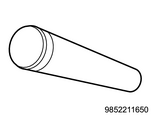
SST: 9-8522-1165-0 - pinion bearing installer
Legend
- 9-8522-1165-0
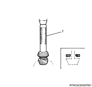
19) Install the collapsible distance piece to the drive pinion.
Caution
- Do not reuse the collapsible distance piece.
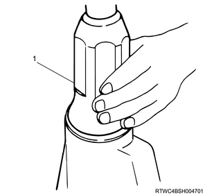
20) Install the drive pinion to the differential carrier.
21) Apply the grease to the oil seal.
22) Install the oil seal and outer bearing inner race to the differential carrier using the special tool.
Caution
- Do not reuse the oil seal.

SST: 5-8840-2165-0 - oil seal installer
Legend
- 5-8840-2165-0
23) Apply differential oil to the threaded portion of the drive pinion.
24) Temporarily tighten the flange to the drive pinion using the special tool.
Caution
- Do not reuse the flange nut.
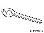
SST: 5-8840-0133-0(J-8614-11) - flange holder
Legend
- 5-8840-0133-0
25) Measure the pinion bearing preload.
Standard: 0.7 to 1.3 N・m { 0.1 to 0.1 kgf・m / 6 to 12 lb・in } Starting torque
Caution
- If the pinion bearing preload is outside the specified range, adjust by further tightening or loosening the flange nut.
Tightening torque: 245 to 294 N・m { 25.0 to 30.0 kgf・m / 181 to 217 lb・ft }
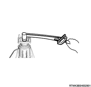
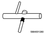
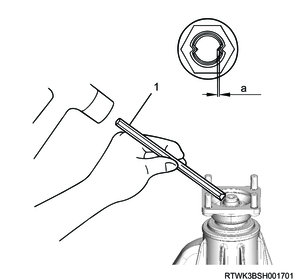
26) Stake the flange nut in 2 locations using the special tool and hammer.
Caution
- When staking, rotate the nut to confirm the correct preload.

SST: 5-8840-2293-0 - end nut lock punch
Legend
- 5-8840-2293-0
Standard value
a: 1.5 mm or less { 0.06 in or less }
27) Measure the pinion bearing preload.
Standard: 0.7 to 1.3 N・m { 0.1 to 0.1 kgf・m / 6 to 12 lb・in } Starting torque
28) Install the side bearing inner race to the differential cage using the special tool.
SST: 5-8840-2162-0 - side bearing installer
SST: 5-8840-0007-0 - grip
Legend
- 5-8840-0007-0
- 5-8840-2162-0
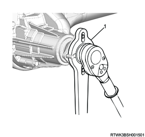
29) Install the differential lock position switch.
Tightening torque: 9.0 N・m { 0.9 kgf・m / 80 lb・in }
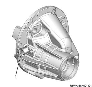
Legend
- Differential lock position switch
30) Install the intermediate connector.
Caution
- Do not reuse the intermediate connector.
Tightening torque: 9.0 N・m { 0.9 kgf・m / 80 lb・in }
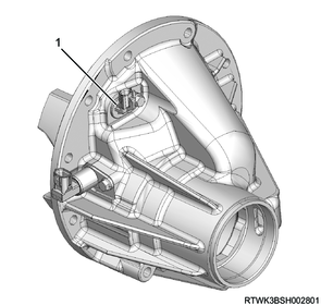
Legend
- Intermediate connector
31) Install the side bearing outer race to the differential cage.
32) Install the differential cage to the differential carrier.
33) Install the coil assembly connector.
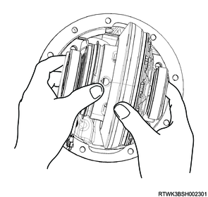
34) Insert the 2 feeler gauges so that the backlash between the left and right side bearing outer races and the differential carrier is 0.
Note
- Securely insert the feeler gauge all the way to the bottom of the bearing.
35) Install the special tool to the differential carrier.
Note
- Install the special tool so that it makes contact perpendicularly with the gear teeth of the ring gear.
SST: 5-8840-0126-0 - dial indicator
Legend
- 5-8840-0126-0
36) Change the left and right feeler gauge thicknesses and adjust the backlash.
Standard: 0.15 to 0.20 mm { 0.006 to 0.008 in }
The dial indicator scale display is in inches.
37) Select a shim based on the thickness of the feeler gauge.
Note
- Select a shim 0.05 mm {0.0020 in} thicker than the feeler gauge.
Caution
- Do not reuse the shim.
38) Disconnect the coil assembly connector.
39) Remove the differential cage from the differential carrier.
40) Remove the side bearing outer race from the differential cage.
Caution
- When removing the bearings, keep them organized so the combinations of the left/right installation positions and bearing race are not mixed up.
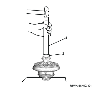
41) Remove the side bearing inner race from the differential cage using the special tool.
SST: 9-8521-0152-2 - bearing remover
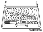
SST: 5-8840-2863-0 - driver tool set
42) Install the shim and side bearing inner race to the differential cage using the special tool.
SST: 5-8840-2162-0 - side bearing installer
SST: 5-8840-0007-0 - grip
Legend
- 5-8840-0007-0
- 5-8840-2162-0
43) Install the side bearing outer race to the differential cage.
44) Install the differential cage to the differential carrier.
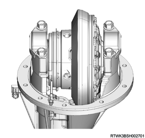
45) Install the bearing cap to the differential carrier.
Note
- Install according to the alignment marks applied during disassembly.
Tightening torque: 108 N・m { 11.0 kgf・m / 80 lb・ft }
Legend
- Alignment mark
46) Measure the runout of the ring gear using the dial gauge.
Limit: 0.05 mm or less { 0.002 in or less }
Note
- Measure the runout of the ring gear at its rear surface.
47) Clean the gear teeth of the ring gear and of the drive pinion.
48) Apply red lead primer to the gear teeth of the ring gear.
Note
- Apply to both surfaces of 7 to 8 gear teeth.
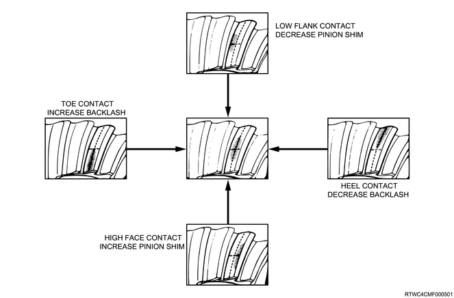
49) Slightly move the ring gear while holding the drive pinion by hand, and inspect the tooth contact of the ring gear and drive pinion.
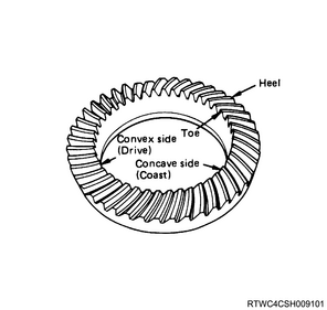
Caution
- Refer to the following diagram to adjust the positions of the ring gear and drive pinion if the tooth contact of the ring gear and drive pinion is found to be incorrect as a result of the inspection.