1. Component views
Rocker arm shaft
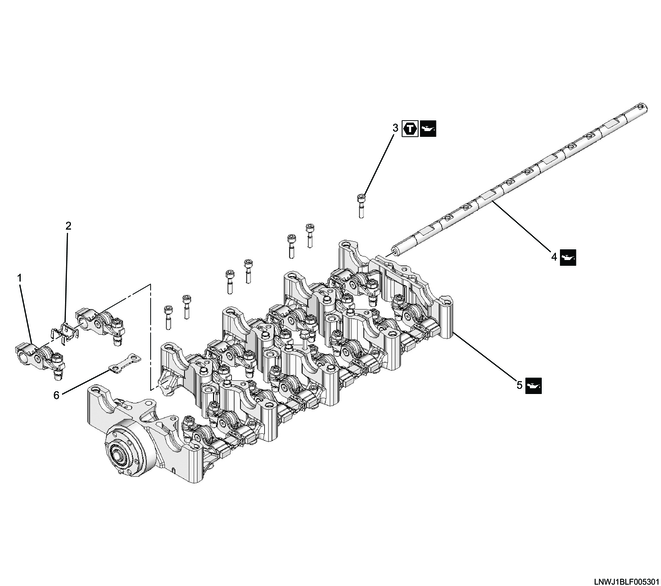
Part name
- Rocker arm
- Spacer
- Bolt
- Rocker arm shaft
- Camshaft bracket
- Plate
Tightening torque
3: 14 N・m { 1.4 kgf・m / 124 lb・in } Wet
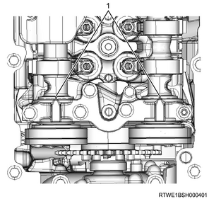
2. Rocker arm shaft installation
1) Put the plate on the camshaft bracket.
2) Loosen the adjust screw of the rocker arm.
Note
- Loosen all the adjust screws.
3) Set the camshaft lower brackets in the order of journal number.
Caution
- Check the stamping from No. 2 to No. 4.
4) Install the rocker arm shaft to the camshaft brackets while assembling the rocker arm.
5) Install the spacer to the rocker arm shaft.
6) Apply engine oil to the threaded portions and seating surfaces of the bolts.
7) Temporarily tighten the rocker arm shaft to the camshaft bracket.
Caution
- Check that the plate is securely installed.
8) Final tighten the No. 5 journal section rocker arm shaft to the camshaft bracket.
Note
- Final tighten the bolts other than for the No. 5 journal section after assembling them to the cylinder head.
Tightening torque: 14 N・m { 1.4 kgf・m / 124 lb・in } Wet
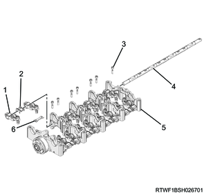
Legend
- Rocker arm
- Spacer
- Bolt
- Rocker arm shaft
- Camshaft bracket
- Plate
9) Apply the engine oil to the camshaft journal.
10) Install the camshaft to the camshaft brackets with the inlet camshaft and exhaust camshaft markings upward.
Caution
- Check the marking on the camshaft upper bracket.
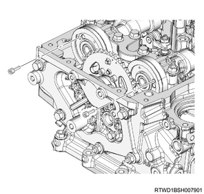
11) Align the camshaft timing marks with idle gear D.
Caution
- Loosen the rocker arm adjust nut and then loosen the adjust screw by 2 pitches or more.
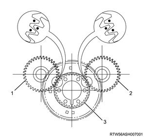
Legend
- Exhaust camshaft gear
- Inlet camshaft gear
- Idle gear D
12) Apply engine oil to the following parts.
- Camshaft upper bracket sliding surface
- Camshaft journal
- Threaded portions and seating surfaces of the M6 bolts
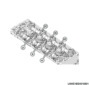
13) Align the inlet camshaft and exhaust camshaft alignment marks with the camshaft upper bracket.
Legend
- Alignment mark
14) Temporarily tighten the camshaft upper bracket M6 bolts to the camshaft brackets.
Caution
- Check the marking on the top surface.
15) Final tighten the camshaft upper bracket M6 bolts to the camshaft brackets.
Tightening torque: 7.0 N・m { 0.7 kgf・m / 62 lb・in } Dry
Tightening torque: 6.0 N・m { 0.6 kgf・m / 53 lb・in } Wet
3. Camshaftbracket installation
1) Rotate the crankshaft in the forward direction (clockwise) to align the No. 1 cylinder piston to compression top dead center.
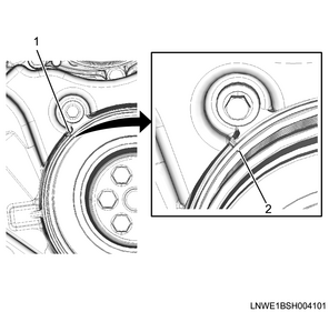
Legend
- Top dead center alignment mark on the gear case cover side
- Crankshaft pulley side top dead center alignment mark
2) Align the camshaft bracket to the cylinder head.
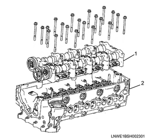
Legend
- Camshaft bracket
- Cylinder head
3) Align the inlet camshaft and exhaust camshaft alignment marks with the camshaft upper bracket.
Caution
- Confirm that the valve cap is correctly installed to the valve stem end.
- Check that the valve cap does not come off or ride up.
Legend
- Alignment mark
4) Apply engine oil to the threaded portions and seating surfaces of the M8 bolts.
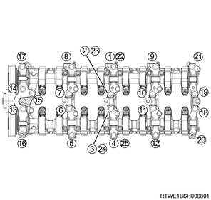
5) Temporarily tighten the camshaft brackets to the cylinder head in the order shown in the diagram.
6) Final tighten the camshaft brackets to the cylinder head in the order shown in the diagram.
Tightening torque: 18 N・m { 1.8 kgf・m / 13 lb・ft } Wet
7) Securely tighten the rocker arm shaft to the camshaft bracket.
Tightening torque: 14 N・m { 1.4 kgf・m / 124 lb・in } Wet
8) Remove the lock bolt from the camshaft gear.
4. Rocker arm adjustment
1) Rotate the crankshaft in the forward direction (clockwise) to align the No. 1 cylinder piston to compression top dead center.
Legend
- Top dead center alignment mark on the gear case cover side
- Crankshaft pulley side top dead center alignment mark
2) Loosen the adjust screw of the rocker arm using the special tool.
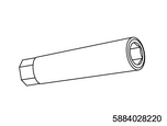
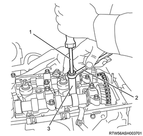
SST: 5-8840-2822-0 - valve clearance adjust nut wrench
Legend
- Screwdriver
- Ring spanner
- 5-8840-2822-0
3) Insert a feeler gauge between the rocker arm roller and the cam.
Note
- Tighten the rocker arm adjust screw, and adjust the valve clearance to the standard value.
Standard: 0.15 mm { 0.0059 in } When cold
4) Lightly tighten the adjust screw with the feeler gauge inserted using the special tool.
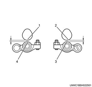
Legend
- Cam (Exhaust side)
- Cam (Inlet side)
- Roller (Inlet side)
- Roller (Exhaust side)
5) Verify that the movement of the feeler gauge becomes stiff.
6) Secure the rocker arm adjust screw with the adjust screw nut.
Tightening torque: 18 N・m { 1.8 kgf・m / 13 lb・ft }
| Cylinder position |
#1 |
#2 |
#3 |
#4 |
||||
| IN |
EX |
IN |
EX |
IN |
EX |
IN |
EX |
|
| No. 1 cylinder compression top dead center |
○ |
○ |
○ |
○ |
||||
| No. 4 cylinder compression top dead center |
○ |
○ |
○ |
○ |
||||
7) Rotate the crankshaft for 1 turn, and adjust any remaining valve clearance.
5. Injector installation
1) Apply engine oil to the O-ring.
2) Install the O-ring to the injector.
Caution
- Do not damage the O-ring.
3) Clean the cylinder head installation surface and injector.
4) Drop the gasket into the port on the cylinder head side.
Caution
- Check that the gasket is seated horizontally.
5) Check that the gasket has been inserted based on the nozzle height using the injector.
Caution
- Do not reuse the leak-off pipe or clip.
- Press the injector in perpendicularly to ensure that the gasket is not slanted.
- Do not hold the injector connector.
- Do not forcibly push the gasket into the injector as it will be pushed until it hits the end of the injector during clamp tightening.

Legend
- Injector
- Leak-off pipe
- Clip
- O-ring
- Gasket
6) Install the injector clamp to the injector.

Legend
- Injector
- Bolt
- Injector clamp
7) Apply engine oil to the threaded portions and seating surfaces of the bolts.
8) Install the injector and injector clamp to the cylinder head.
9) Temporarily tighten the injector clamp bolt to the cylinder head.
6. Injection pipe installation
1) Apply engine oil to the threaded portions of the sleeve nuts on the injector side, as well as the injector O-rings.
2) Temporarily tighten the injection pipes to the common rail (fuel rail) and injectors by hand until the sleeve nuts can no longer turn.
Caution
- Do not reuse the injection pipe.
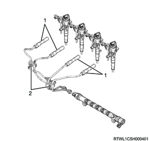
Legend
- Injection pipe
- Clip
3) Temporarily tighten the clip to the injection pipe.
4) Final tighten the injector clamp bolt to the cylinder head.
Tightening torque: 26 N・m { 2.7 kgf・m / 19 lb・ft }
5) Final tighten the injection pipes to the injectors and common rail (fuel rail).
Tightening torque: 44 N・m { 4.5 kgf・m / 32 lb・ft } Injector side
Tightening torque: 44 N・m { 4.5 kgf・m / 32 lb・ft } Common rail (fuel rail) side
6) Securely tighten the clip to the injection pipe.
Tightening torque: 8.0 N・m { 0.8 kgf・m / 71 lb・in }
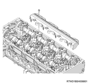
7. Baffle plate installation
1) Install the baffle plate to the cylinder head.
Tightening torque: 10.0 N・m { 1.0 kgf・m / 89 lb・in }
8. Leak-off pipe installation
1) Install the leak-off pipe to the inlet manifold.
Tightening torque: 25 N・m { 2.5 kgf・m / 18 lb・ft }
2) Connect the 2 leak-off hoses to the leak-off pipe.
3) Connect the 3 vacuum hoses to the vacuum pipe.
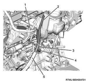
Legend
- Leak-off hose (Injector side)
- Leak-off pipe
- Leak-off hose (Supply pump side)
- Vacuum hose (Swirl control valve side)
- Vacuum hose (Vacuum pump side)
4) Temporarily tighten the harness brackets to the inlet manifold in the order shown in the diagram.

5) Final tighten the harness brackets to the inlet manifold in the order shown in the diagram.
Tightening torque: 10.0 N・m { 1.0 kgf・m / 89 lb・in }
9. Swirl control solenoid valve installation
1) Install the swirl control solenoid valve and bracket as a set to the inlet manifold.
Tightening torque: 25 N・m { 2.5 kgf・m / 18 lb・ft }
2) Connect the vacuum hose to swirl control solenoid valve.
3) Connect the connector to swirl control solenoid valve.
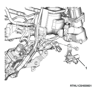
Legend
- Swirl control solenoid valve