1. Component views
Cylinder block
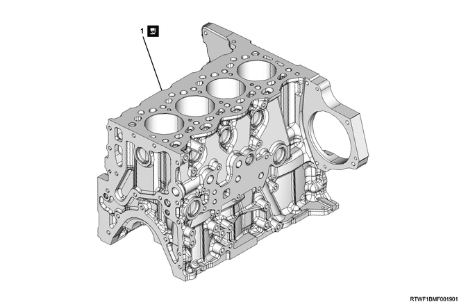
Part name
- Cylinder block
2. Front cover removal
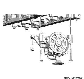
3. Oil pump removal
1) Remove the oil pump from the cylinder block.
4. Piston removal
1) Remove any carbon from the top of the cylinder bore using a scraper.
2) Turn the crankshaft to align it to bottom dead center.
3) Remove the connecting rod bearing cap from the connecting rod.
4) Remove the connecting rod bearing from the connecting rod bearing cap.
Note
- Organize the removed bearings according to the cylinders using tags, etc.

5) Turn the crankshaft to align it to top dead center.
6) Remove the piston and connecting rod from the cylinder block.
Note
- Pull out the piston and connecting rod from the cylinder head side.
- Push out from the lower end of the connecting rod by using the handle of a hammer, etc., so as not to damage the bearing.
Caution
- When pushing out the connecting rod, do not damage the oil jet and cylinder inner surface.
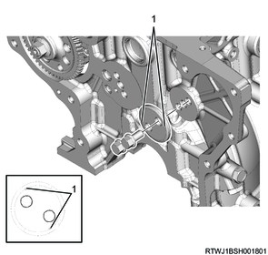
5. Crankshaft removal
1) Measure the crankshaft thrust clearance using a feeler gauge.
Standard: 0.04 to 0.22 mm { 0.0016 to 0.0087 in }
Note
- Replace the thrust bearing if the measured value is outside the standard range.

2) Loosen the bearing cap bolts in the order shown in the diagram.

3) Remove the bearing cap from the cylinder block.
Caution
- Do not reuse the bearing cap bolt.
However, only when a new bearing cap bolt is used to measure the oil clearance, the bearing cap bolt can be reused.
4) Remove the lower crankshaft bearing from the bearing cap.
Note
- If reusing the crankshaft bearings, put number tags on the crankshaft bearings.
5) Remove the crankshaft from the cylinder block.
6) Remove the thrust bearing from the cylinder block.
7) Remove the upper crankshaft bearing from the cylinder block.
Note
- If reusing the crankshaft bearings, put number tags on the crankshaft bearings.
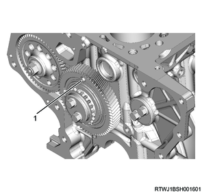
6. Idle gear removal
1) Remove the timing chain guide from the cylinder block.
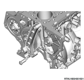
2) Apply the dial gauge to the idle gear tooth to be measured, and gently move the gear left and right to measure the fluctuation of the dial gauge.
Note
- If the measured value exceeds the limit, replace the idle gear.
Standard: 0.10 to 0.17 mm { 0.0039 to 0.0067 in }
Limit: 0.30 mm { 0.0118 in }
3) Measure the idle gear axial direction clearance using a feeler gauge.
Note
- Replace the idle gear or thrust collar if the measured value exceeds the limit.
Standard: 0.060 to 0.135 mm { 0.0024 to 0.0053 in }
Limit: 0.20 mm { 0.0079 in }
4) Install the M5 bolts for securing the sub gear to idle gear A.
Legend
- M5 bolt
5) Remove the flange from idle gear A.
6) Remove idle gear A from the idle gear A shaft.
7) Remove the idle gear A shaft from the cylinder block.

Legend
- Front mark
8) Remove the flange from the cylinder block.
Legend
- Front mark
7. Fuel supply pump removal
1) Disconnect the connector from the fuel temperature sensor.
2) Disconnect the connector from the FRP regulator.

Legend
- FRP regulator connector
- Fuel temperature sensor connector
3) Disconnect the fuel suction hose from the fuel supply pump.
4) Disconnect the fuel leak-off hose from the fuel supply pump.

Legend
- Fuel leak-off hose
- Fuel suction hose
5) Remove the fuel supply pump and adapter from the cylinder block.
Caution
- Do not hold the high pressure pipe.
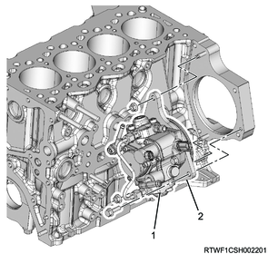
Legend
- Fuel supply pump
- Adapter
8. Oil filter removal
1) Remove the oil filter and gasket from the cylinder block.
Caution
- Do not reuse the gasket.
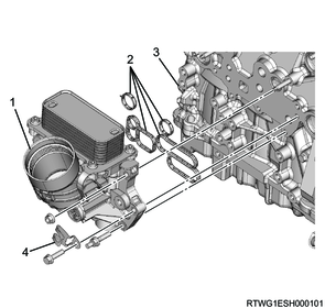
Legend
- Oil filter
- Gasket
- Cylinder block
- Clip
9. EGR cooler water pipe removal
1. Manual transmission models
1) Remove EGR cooler water pipe B and EGR cooler water hose from the cylinder block.
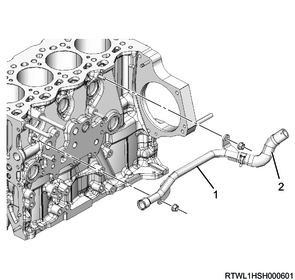
Legend
- EGR cooler water pipe B
- EGR cooler water hose
2. Automatic transmission models
1) Remove EGR cooler water pipe B from the cylinder block.
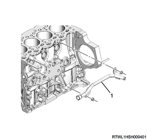
Legend
- EGR cooler water pipe B
10. Engine foot removal
1) Remove the right side engine foot from the cylinder block.
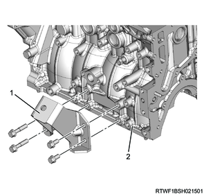
Legend
- Right side engine foot
- Cylinder block
2) Remove the left side engine foot from the cylinder block.
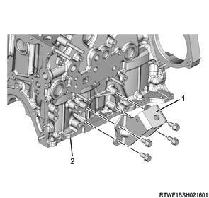
Legend
- Left side engine foot
- Cylinder block
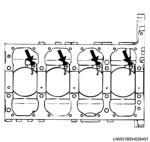
11. Piston oil jet removal
1) Remove the piston oil jet from the cylinder block.
Caution
- Do not damage or deform the oil jet pipe nozzle.